Advanced Wind Turbine Program Next Generation Turbine ... - NREL
Advanced Wind Turbine Program Next Generation Turbine ... - NREL
Advanced Wind Turbine Program Next Generation Turbine ... - NREL

You also want an ePaper? Increase the reach of your titles
YUMPU automatically turns print PDFs into web optimized ePapers that Google loves.
3.2.3 Mechanical Loads Testing of the POC <strong>Turbine</strong>................................................... 58<br />
3.2.4 Acoustic Noise Testing of the POC <strong>Turbine</strong>........................................................ 59<br />
3.3 POC Certification ............................................................................................................ 59<br />
4 Engineering and Manufacturing Development <strong>Turbine</strong>, EMD1.5/77..................................... 61<br />
4.1 IEC Class S High Energy Capture Rotor Configuration and Loads ............................... 61<br />
4.2 EMD1.5/77 Component Designs .................................................................................... 65<br />
4.2.1 EMD Gearbox Modification ................................................................................ 65<br />
4.2.2 EMD 37-m Rotor Blade Design and Testing ....................................................... 65<br />
4.2.3 EMD Controls Systems ........................................................................................ 67<br />
4.2.3.1 Tower-top Accelerometer Feedback ...................................................... 67<br />
4.2.3.2 Rotor Feedback Control ......................................................................... 69<br />
4.3 Installation and Testing of the EMD <strong>Turbine</strong> ................................................................. 70<br />
4.3.1 Power Performance Testing of the EMD <strong>Turbine</strong> ............................................... 71<br />
4.3.2 Mechanical Loads Testing of the EMD <strong>Turbine</strong>.................................................. 72<br />
4.3.3 Acoustic Noise Testing of the EMD <strong>Turbine</strong>....................................................... 72<br />
4.3.4 Testing of Asymmetric Load Control System...................................................... 73<br />
5 Commercialization of GE NGT Technology .......................................................................... 74<br />
6 Conclusions ............................................................................................................................. 75<br />
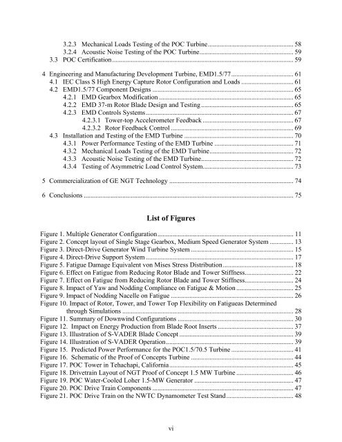
List of Figures<br />
Figure 1. Multiple Generator Configuration................................................................................. 11<br />
Figure 2. Concept layout of Single Stage Gearbox, Medium Speed Generator System .............. 13<br />
Figure 3. Direct-Drive Generator <strong>Wind</strong> <strong>Turbine</strong> System ............................................................. 15<br />
Figure 4. Direct-Drive Support System ........................................................................................ 17<br />
Figure 5. Fatigue Damage Equivalent von Mises Stress Distribution .......................................... 18<br />
Figure 6. Effect on Fatigue from Reducing Rotor Blade and Tower Stiffness............................. 22<br />
Figure 7. Effect on Fatigue from Reducing Rotor Blade and Tower Stiffness............................. 24<br />
Figure 8. Impact of Yaw and Nodding Compliance on Fatigue & Motion .................................. 25<br />
Figure 9. Impact of Nodding Nacelle on Fatigue ......................................................................... 26<br />
Figure 10. Impact of Rotor, Tower, and Tower Top Flexibility on Fatigueas Determined<br />
through Simulations ...................................................................................................... 28<br />
Figure 11. Summary of Downwind Configurations ..................................................................... 30<br />
Figure 12. Impact on Energy Production from Blade Root Inserts ............................................. 37<br />
Figure 13. Illustration of S-VADER Blade Concept .................................................................... 39<br />
Figure 14. Illustration of S-VADER Operation............................................................................ 39<br />
Figure 15. Predicted Power Performance for the POC1.5/70.5 <strong>Turbine</strong> ..................................... 41<br />
Figure 16. Schematic of the Proof of Concepts <strong>Turbine</strong> ............................................................. 44<br />
Figure 17. POC Tower in Tehachapi, California .......................................................................... 45<br />
Figure 18. Drivetrain Layout of NGT Proof of Concept 1.5 MW <strong>Turbine</strong> .................................. 46<br />
Figure 19. POC Water-Cooled Loher 1.5-MW Generator ........................................................... 47<br />
Figure 20. POC Drive Train Components .................................................................................... 47<br />
Figure 21. POC Drive Train on the NWTC Dynamometer Test Stand ........................................ 48<br />
vi