Advanced Wind Turbine Program Next Generation Turbine ... - NREL
Advanced Wind Turbine Program Next Generation Turbine ... - NREL
Advanced Wind Turbine Program Next Generation Turbine ... - NREL

Create successful ePaper yourself
Turn your PDF publications into a flip-book with our unique Google optimized e-Paper software.
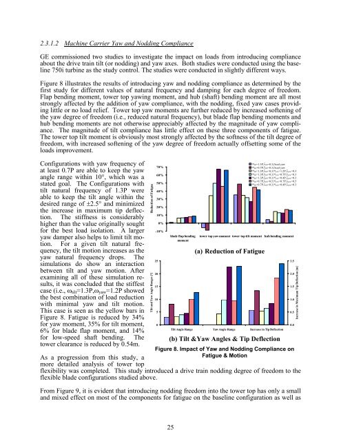
2.3.1.2 Machine Carrier Yaw and Nodding Compliance<br />
GE commissioned two studies to investigate the impact on loads from introducing compliance<br />
about the drive train tilt (or nodding) and yaw axes. Both studies were conducted using the baseline<br />
750i turbine as the study control. The studies were conducted in slightly different ways.<br />
Figure 8 illustrates the results of introducing yaw and nodding compliance as determined by the<br />
first study for different values of natural frequency and damping for each degree of freedom.<br />
Flap bending moment, tower top yawing moment, and hub (shaft) bending moment are all most<br />
strongly affected by the addition of yaw compliance, with the nodding, fixed yaw cases providing<br />
little or no load relief. Tower top yaw moments are further reduced by increased softening of<br />
the yaw degree of freedom (i.e., reduced natural frequency), but blade flap bending moments and<br />
hub bending moments are not otherwise appreciably affected by the magnitude of yaw compliance.<br />
The magnitude of tilt compliance has little effect on these three components of fatigue.<br />
The tower top tilt moment is obviously most strongly affected by the softness of the tilt degree of<br />
freedom, with increased softening of the yaw degree of freedom actually offsetting some of the<br />
loads improvement.<br />
Configurations with yaw frequency of<br />
at least 0.7P are able to keep the yaw<br />
70%<br />
angle range within 10°, which was a<br />
60%<br />
stated goal. The Configurations with 50%<br />
tilt natural frequency of 1.3P were 40%<br />
able to keep the tilt angle within the<br />
desired range of ±2.5° and minimized<br />
the increase in maximum tip deflec<br />
30%<br />
tion. The stiffness is considerably<br />
10%<br />
higher than the value originally sought 0%<br />
for the best load isolation. A larger<br />
yaw damper also helps to limit tilt motion.<br />
For a given tilt natural frequency,<br />
the tilt motion increases as the<br />
-10%<br />
yaw natural frequency drops. The<br />
simulations do show an interaction<br />
25<br />
20%<br />
between tilt and yaw motion. After<br />
examining all of these simulation re<br />
sults, it was concluded that the stiffest 15<br />
case (i.e., ωtilt=1.3P,ωyaw=1.2P showed<br />
the best combination of load reduction<br />
with minimal yaw and tilt motion.<br />
This case is seen as the yellow bars in<br />
Figure 8. Fatigue is reduced by 34%<br />
Tilt and Ya w Angle Ranges [°] Reduction of Fatigue<br />
20<br />
10<br />
5<br />
ωSeries1 tilt=1.3P, ζtilt=0.3,fixed<br />
yaw<br />
ωSeries2 tilt=0.7P, ζtilt=0.3,fixed<br />
yaw<br />
ωSeries3 tilt=1.3P, ζtilt=0.3, ωyaw=1.2P, ζyaw=0.3 ωSeries4 tilt=1.3P, ζtilt=0.3, ωyaw=0.7P, ζyaw=0.3 ωSeries5 tilt=1.3P, ζtilt=0.3, ωyaw=0.4P, ζyaw=0.3 ωSeries6 tilt=0.7P, ζtilt=0.5, ωyaw=0.7P, ζyaw=0.5 ω Series7 tilt=0.7P,ζ tilt=0.3 ,ωyaw =0.4P ,ζyaw=0.3 blade flap bending tower top yaw moment tower top tilt moment hub bending moment<br />
moment<br />
(a) Reduction of Fatigue<br />
for yaw moment, 35% for tilt moment, 0<br />
0.0<br />
6% for blade flap moment, and 14%<br />
Tilt Angle Range Yaw Angle Range Increase in Tip Deflection<br />
for low-speed shaft bending. The<br />
tower clearance is reduced by 0.54m.<br />
(b) Tilt &Yaw Angles & Tip Deflection<br />
Figure 8. Impact of Yaw and Nodding Compliance on<br />
As a progression from this study, a<br />
more detailed analysis of tower top<br />
Fatigue & Motion<br />
flexibility was completed. This study introduced a drive train nodding degree of freedom to the<br />
flexible blade configurations studied above.<br />
From Figure 9, it is evident that introducing nodding freedom into the tower top has only a small<br />
and mixed effect on most of the components for fatigue on the baseline configuration as well as<br />
25<br />
2.5<br />
2.0<br />
1.5<br />
1.0<br />
0.5<br />
Increase in Maximum Tip Deflection [m]