Advanced Wind Turbine Program Next Generation Turbine ... - NREL
Advanced Wind Turbine Program Next Generation Turbine ... - NREL
Advanced Wind Turbine Program Next Generation Turbine ... - NREL

You also want an ePaper? Increase the reach of your titles
YUMPU automatically turns print PDFs into web optimized ePapers that Google loves.
A finite element model of the blade structure was built in ANSYS and used to analyze the blade's<br />
structural integrity with respect to:<br />
• Tip deflection<br />
• Buckling stability<br />
• Extreme strain<br />
• Laminate Fatigue<br />
• Root attachment failure due to fatigue, extreme static loads, and flange liftoff<br />
• Natural frequency requirements.<br />
Structural analyses showed that tip deflection constraints were the overriding design driver. The<br />
target tip deflection was 65% of tower clearance. Forward coning was added to the blade at the<br />
5.5-m station in order to provide an additional 0.7-m of tip offset and reduce spar cap material<br />
usage. Coning from 5.5 m keeps most mass on the pitch axis. Nevertheless, tip deflection requirements<br />
still required an increase in blade mass. Full-scale tests indicated that 59.7% of tower<br />
clearance was being consumed, versus the 70% maximum allowed by Germanischer-Lloyd. The<br />
maximum strain on the blade is well below the strain allowable. Fatigue damage remains everywhere<br />
under unity. Buckling analyses indicated that no core material was needed in the spar cap.<br />
The POC blade design departs from the approach used by the baseline 750-kW turbine's 24-m<br />
blades, which employ balsa in the spar cap for buckling resistance. By narrowing and thickening<br />
the spar cap of the POC blade, the use of balsa was avoided for equal cost. The GE34a uses a Tbolt<br />
root attachment developed in the 750-kW NTRT program. The blade uses 54 M30 T-bolts.<br />
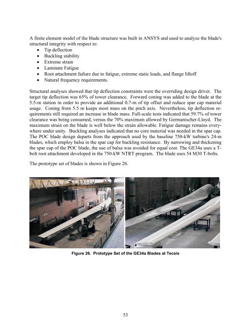
The prototype set of blades is shown in Figure 26.<br />
Figure 26. Prototype Set of the GE34a Blades at Tecsis<br />
53