Manual for the Design of Pipe Systems and Pumps - GEA ...
Manual for the Design of Pipe Systems and Pumps - GEA ...
Manual for the Design of Pipe Systems and Pumps - GEA ...

Create successful ePaper yourself
Turn your PDF publications into a flip-book with our unique Google optimized e-Paper software.
5.3 Suction pipe<br />
5.4 Delivery pipe<br />
It is important <strong>for</strong> most <strong>of</strong> <strong>the</strong> pumps - but especially <strong>for</strong> non-selfpriming centrifugal pumps -<br />
that no air is drawn into <strong>the</strong> pump - as o<strong>the</strong>rwise this would impair <strong>the</strong> pump per<strong>for</strong>mance.<br />
In <strong>the</strong> worst case <strong>the</strong> pump would stop pumping. There<strong>for</strong>e <strong>the</strong> tanks should be designed <strong>and</strong><br />
constructed in a way that no air-drawing turbulences occur. This can be avoided by installing<br />
a vortex breaker into <strong>the</strong> tank outlet.<br />
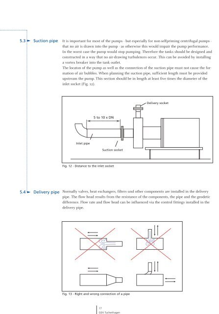
The locaton <strong>of</strong> <strong>the</strong> pump as well as <strong>the</strong> connection <strong>of</strong> <strong>the</strong> suction pipe must not cause <strong>the</strong> <strong>for</strong>mation<br />
<strong>of</strong> air bubbles. When planning <strong>the</strong> suction pipe, sufficient length must be provided<br />
upstream <strong>the</strong> pump. This section should be in length at least five times <strong>the</strong> diameter <strong>of</strong> <strong>the</strong><br />
inlet socket (Fig. 12).<br />
Inlet pipe<br />
5 to 10 x DN<br />
Suction socket<br />
Fig. 12 - Distance to <strong>the</strong> inlet socket<br />
Normally valves, heat exchangers, filters und o<strong>the</strong>r components are installed in <strong>the</strong> delivery<br />
pipe. The flow head results from <strong>the</strong> resistance <strong>of</strong> <strong>the</strong> components, <strong>the</strong> pipe <strong>and</strong> <strong>the</strong> geodetic<br />
difference. Flow rate <strong>and</strong> flow head can be influenced via <strong>the</strong> control fittings installed in <strong>the</strong><br />
delivery pipe.<br />
Fig. 13 - Right <strong>and</strong> wrong connection <strong>of</strong> a pipe<br />
17<br />
<strong>GEA</strong> Tuchenhagen<br />
Delivery socket