Manual for the Design of Pipe Systems and Pumps - GEA ...
Manual for the Design of Pipe Systems and Pumps - GEA ...
Manual for the Design of Pipe Systems and Pumps - GEA ...

Create successful ePaper yourself
Turn your PDF publications into a flip-book with our unique Google optimized e-Paper software.
6.1.2 Explanations<br />
6.1.3 Calculation<br />
<strong>of</strong> <strong>the</strong> NPSH<br />
The flow rate is 24 m 3 /h. Components <strong>and</strong> process units are installed in <strong>the</strong> pipe between<br />
Tank A to be emptied <strong>and</strong> Tank B to be filled. As already mentioned be<strong>for</strong>e, it is essential to<br />
install <strong>the</strong> pump as close as possible to <strong>the</strong> tank to be emptied.<br />
Between Tank A <strong>and</strong> <strong>the</strong> pump are located a butterfly valve <strong>and</strong> two double seat valves as<br />
well as one reducer <strong>and</strong> 5 bends <strong>and</strong> finally 10 m pipe in DN 65.<br />
In <strong>the</strong> pipe from <strong>the</strong> pump up to Tank B (20 m in DN 50) are installed a double seat valve, a<br />
single seat valve, one heat exchanger <strong>and</strong> one spray ball. The difference in elevation <strong>of</strong> <strong>the</strong><br />
liquid level in Tank A to Tank B is 6 m. Now <strong>the</strong> metre equivalent pipe length must be determined<br />
<strong>for</strong> each component installed. For this purpose see <strong>the</strong> st<strong>and</strong>ard tables <strong>for</strong> pressure<br />
drops on Page 37 <strong>and</strong> 38. The outcome is in total 40.18 m on <strong>the</strong> suction side. This value is<br />
converted into <strong>the</strong> corresponding pressure drop (H) <strong>of</strong> <strong>the</strong> pipe, cross section DN 65.<br />
According to <strong>the</strong> table, <strong>the</strong> pressure drop is 6.5 m per 100 m at a flow rate <strong>of</strong> 24 m 3 /h <strong>and</strong><br />
with a pipe DN 65. Based on 40.18 m, <strong>the</strong> pressure drop (H v,s) is 2.61 m. Downstream <strong>the</strong><br />
pump, <strong>the</strong> liquid must be conveyed in length equivalent pipe <strong>of</strong> 37.2 m in total. The pressure<br />
drop <strong>of</strong> a pipe in DN 50 is according to <strong>the</strong> table 25 m per 100 m. Based on 37.2 m,<br />
<strong>the</strong> pressure drop is 7.4 m. In addition, on <strong>the</strong> delivery side <strong>the</strong>re is a heat exchanger with a<br />
pressure drop <strong>of</strong> 12 m (at 24 m 3 ) as well as a spray ball at <strong>the</strong> end <strong>of</strong> <strong>the</strong> pipe with a pressure<br />
drop <strong>of</strong> 5 m.<br />
In total <strong>the</strong> pressure drop on <strong>the</strong> delivery side (H v,d) is 24.4 m.<br />
The sum <strong>of</strong> pressure drops on <strong>the</strong> suction side (H v,s), on <strong>the</strong> delivery side (H v,d) <strong>and</strong> <strong>the</strong><br />
geodetic flow head (H geo), result in a total pressure drop (H A) <strong>of</strong> 33.0 m that must be<br />
compensated by <strong>the</strong> pump.<br />
The next step is <strong>the</strong> calculation <strong>of</strong> <strong>the</strong> NPSH <strong>of</strong> <strong>the</strong> plant that finally complete <strong>the</strong> parameters<br />
needed <strong>for</strong> <strong>the</strong> design <strong>of</strong> your pump.<br />
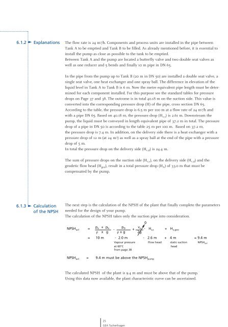
The calculation <strong>of</strong> <strong>the</strong> NPSH takes only <strong>the</strong> suction pipe into consideration.<br />
NPSHavl =<br />
pe + pb pD -<br />
ρ x g ρ x g<br />
+<br />
ve 2g<br />
0<br />
- Hv,s + Hz,geo = 10 m - 2.0 m - 2.6 m + 4 m = 9.4 m<br />
Vapour pressure Flow head static suction NPSHavl at 60°C<br />
from page 38<br />
head<br />
NPSH avl = 9.4 m must be above <strong>the</strong> NPSH pump<br />
The calculated NPSH <strong>of</strong> <strong>the</strong> plant is 9.4 m <strong>and</strong> must be above that <strong>of</strong> <strong>the</strong> pump.<br />
Using this data now available, <strong>the</strong> plant characteristic curve can be ascertained.<br />
25<br />
<strong>GEA</strong> Tuchenhagen