Manual for the Design of Pipe Systems and Pumps - GEA ...
Manual for the Design of Pipe Systems and Pumps - GEA ...
Manual for the Design of Pipe Systems and Pumps - GEA ...

You also want an ePaper? Increase the reach of your titles
YUMPU automatically turns print PDFs into web optimized ePapers that Google loves.
7.5 Result<br />
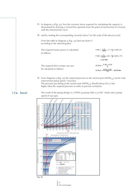
7. In diagram 4 (Fig. 32), first <strong>the</strong> viscosity factor required <strong>for</strong> calculat ing <strong>the</strong> capacity is<br />
determined by draw ing a vertical line upwards from <strong>the</strong> point <strong>of</strong> intersection <strong>of</strong> viscosity<br />
with <strong>the</strong> characteristic curve<br />
8. <strong>and</strong> by reading <strong>the</strong> corres ponding viscosity factor f on <strong>the</strong> scale <strong>of</strong> <strong>the</strong> abscissa (2.8)<br />
From <strong>the</strong> table in Diagram 4 (Fig. 32) find out factor S<br />
according to <strong>the</strong> selected gasket.<br />
The required motor power is calculated<br />
as follows:<br />
The required drive torque can now<br />
be calculated as follows:<br />
9. From Diagram 5 (Fig. 32) <strong>the</strong> required pressure at <strong>the</strong> suction port (NSPH req) can be read<br />
(intersection pump speed / viscosity).<br />
The pressure prevailing at <strong>the</strong> suction port (NPSH avl) should always be 0.1 bar<br />
higher than <strong>the</strong> required pres sure in order to prevent cavitation.<br />
er<strong>for</strong>derlicher Druck am Saugstutzen (bar abs.)<br />
net inlet pressure required - N.I.P.R. - (bar absolute)<br />
1.000.000<br />
Viskosität (cp) / Viscosity (cp)<br />
100.000<br />
10.000<br />
The result <strong>of</strong> <strong>the</strong> pump design is a VPSH 54 pump with a 3.0 kW motor <strong>and</strong> a pump<br />
speed <strong>of</strong> 750 rpm.<br />
2,0<br />
1,8<br />
1,6<br />
1,4<br />
1,2<br />
1,0<br />
0,8<br />
0,6<br />
0,4<br />
0,27<br />
0,2<br />
0<br />
1.000<br />
100<br />
10<br />
Fig. 32<br />
atmospheric<br />
pressure<br />
100 200 300 400 500 600 700 800<br />
715<br />
900 1000 1100 1200 1300 1400 1500<br />
2,8<br />
Pumpendrehzahl (U/min.) / Pump speed (rpm)<br />
Viskositätsfaktor f / Viscosity factor f<br />
2 4 6 8 10 12 14 16 18 20 22 24 26<br />
8<br />
7<br />
100.000 cp<br />
30.000 cp<br />
Diagramm 4<br />
10.000 cp<br />
9<br />
3.000 cp<br />
Kraftbedarf / Power Absorbed<br />
Dichtung Typ Code Faktor S<br />
Seal Type Code Factor S<br />
Einfach / Single C/SS 8 1<br />
Einfach / Single C/SIC 3 1<br />
Einfach / Single SIC/SIC 2 2<br />
Doppelt / Double C/SIC 4 2<br />
Doppelt / Double SIC/SIC 1 3<br />
p<br />
P (W) = ( + f + S x 0.455 x N<br />
0.61 )<br />
P (W) x 9.56<br />
M (Nm) =<br />
N<br />
p = Differenzdruck / Differential pressure (bar)<br />
N = Drehzahl (U/min) / Speed in rpm<br />
f = Viskositätsfaktor aus dem Diagramm /<br />
Viscosity factor from graph<br />
S = Dichtung (siehe Tabelle) /<br />
Seal factor from table<br />
P = Leistung / Power (W)<br />
M = Drehmoment / Torque (Nm)<br />
35<br />
<strong>GEA</strong> Tuchenhagen<br />
max. Drehzahl / max. speed<br />
Diagramm 5<br />
1.000 cp<br />
300 cp<br />
100 cp<br />
10 cp<br />
1 cp<br />
NIPR<br />
atmosphärischer<br />
Druck<br />
Technische Daten / Application Data<br />
Max. Wellendrehmoment /<br />
Max. input shaft torque (Nm) 150<br />
Max. radiale Wellenbelastung /<br />
Max. shaft radial load (N) 2250<br />
Max. Partikelgröße (weich) /<br />
Max. s<strong>of</strong>t particle dia. (mm) 15<br />
Verdrängung / Displacement (cc/rev) 455<br />
Verdrängung /<br />
Displacement (litres/100revs) 45.5<br />
Physikalische Daten / Physical Data<br />
Gewicht der Pumpe ohne Antrieb /<br />
Bareshaft pump weight (kg) 35<br />
Ölvolumen / Oil capacity (cc) 1100<br />
Rückhaltevolumen /<br />
Hold up volume (cc) 820<br />
(horizontale Anschlüsse) /<br />
(horizontal ports)<br />
Anzugsmomente / Tightening Torques (Nm)<br />
Enddeckelbolzen / End cover bolts 20<br />
Rotorschrauben / Rotor retainer screws 55<br />
Rotorgehäuseschrauben /<br />
Rotor case screws 20<br />
Getriebedeckelschrauben /<br />
Gear cover screws 15<br />
Zahnradmuttern / Gear nuts 100<br />
Rotorzugstangenschrauben VPSU /<br />
Rotor tie rod nuts 40<br />
Rotortoleranzen / Rotor Clearances (mm)<br />
Vorne, Rotor zum Deckel /<br />
Front, rotor to end cover 0.15<br />
Radial, Rotor zum Rotorgehäuse /<br />
Radial, rotor to rotor case 0.25<br />
Rotor zu Rotor / Mesh, lobe to lobe - min 0.20<br />
p<br />
P (W) = 0.61 + f + S x 0.265 x N<br />
( )<br />
5<br />
P (W) = +2,8 + 1 x 0.265 x 715<br />
0.61<br />
( )<br />
= 2.27 kW<br />
P (W) x 9.56<br />
M (Nm) =<br />
N<br />
M (Nm) = 2270 x 9.56 = 30.35 Nm<br />
715