Manual for the Design of Pipe Systems and Pumps - GEA ...
Manual for the Design of Pipe Systems and Pumps - GEA ...
Manual for the Design of Pipe Systems and Pumps - GEA ...

You also want an ePaper? Increase the reach of your titles
YUMPU automatically turns print PDFs into web optimized ePapers that Google loves.
6.3.3 Reducing <strong>the</strong><br />
impeller size<br />
6.3.4 Operation in<br />
parallel<br />
6.3.5 Operation in<br />
series<br />
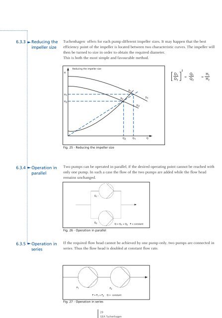
Tuchenhagen <strong>of</strong>fers <strong>for</strong> each pump different impeller sizes. It may happen that <strong>the</strong> best<br />
efficiency point <strong>of</strong> <strong>the</strong> impeller is located between two characteristic curves. The impeller will<br />
<strong>the</strong>n be turned to size in order to obtain <strong>the</strong> required diameter.<br />
This is both <strong>the</strong> most simple <strong>and</strong> favourable method.<br />
H<br />
H 1<br />
H 2<br />
Reducing Impeller <strong>the</strong> reduced impeller size<br />
picture 4<br />
Fig. 25 - Reducing <strong>the</strong> impeller size<br />
Two pumps can be operated in parallel, if <strong>the</strong> desired operating point cannot be reached with<br />
only one pump. In such a case <strong>the</strong> flow <strong>of</strong> <strong>the</strong> two pumps are added while <strong>the</strong> flow head<br />
remains unchanged.<br />
Q 1<br />
Q 2<br />
Fig. 26 - Operation in parallel<br />
B 2<br />
If <strong>the</strong> required flow head cannot be achieved by one pump only, two pumps are connected in<br />
series. Thus <strong>the</strong> flow head is doubled at constant flow rate.<br />
P 1 P2<br />
Fig. 27 - Operation in series<br />
P = P 1 + P 2 Q = constant<br />
29<br />
<strong>GEA</strong> Tuchenhagen<br />
B 1<br />
D 2<br />
D 1<br />
Q 2 Q 1 Q<br />
Q = Q 1 + Q 2 P = constant<br />
D 1<br />
D 2<br />
2<br />
Q1 Q2 ≈ ≈<br />
H 1<br />
H 2