Manual for the Design of Pipe Systems and Pumps - GEA ...
Manual for the Design of Pipe Systems and Pumps - GEA ...
Manual for the Design of Pipe Systems and Pumps - GEA ...

Create successful ePaper yourself
Turn your PDF publications into a flip-book with our unique Google optimized e-Paper software.
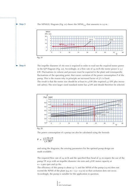
Step 3<br />
Step 4<br />
The NPSH/Q Diagram (Fig. 21) shows <strong>the</strong> NPSH req, that amounts to 1.9 m.<br />
Fig. 21<br />
The impeller diameter <strong>of</strong> 160 mm is required in order to read out <strong>the</strong> required motor power<br />
in <strong>the</strong> Q/P Diagram (Fig. 22). Accordingly, at a flow rate <strong>of</strong> 24 m 3/h <strong>the</strong> motor power is 3.7<br />
kW. Fluctuations in volume <strong>and</strong> pressure must be expected in <strong>the</strong> plant <strong>and</strong> consequently<br />
fluctuations <strong>of</strong> <strong>the</strong> operating point, that causes variation <strong>of</strong> <strong>the</strong> power consumption P <strong>of</strong> <strong>the</strong><br />
pump. This is <strong>the</strong> reason why in principle an increased factor <strong>of</strong> 5% is fixed.<br />
The result is that <strong>the</strong> motor size should be at least to 4 kW (<strong>the</strong> required 3.7 kW plus increased<br />
safety). The next larger sized st<strong>and</strong>ard motor has 4 kW <strong>and</strong> should <strong>the</strong>re<strong>for</strong>e be selected.<br />
Fig. 22<br />
The power consumption <strong>of</strong> a pump can also be calculated using <strong>the</strong> <strong>for</strong>mula<br />
P =<br />
NPSH<br />
[ft] [m]<br />
20 6<br />
5<br />
15<br />
4<br />
10 3<br />
2<br />
5<br />
1<br />
0 0<br />
0<br />
P<br />
[hp] [kW]<br />
5,0<br />
6,0<br />
5,0<br />
4,0<br />
3,0<br />
2,0<br />
1,0<br />
4,5<br />
4,0<br />
3,5<br />
3,0<br />
2,5<br />
2,0<br />
1,5<br />
1,0<br />
0 5 10 15 20 25 30 35<br />
Q<br />
ρ x Q x H<br />
η x 367<br />
NPSH req = 1.9 m<br />
5 10 15 20 25 30 35<br />
P = 3.7 kw<br />
<strong>and</strong> using <strong>the</strong> diagrams, <strong>the</strong> missing parameters <strong>for</strong> <strong>the</strong> optimal pump design are<br />
made available.<br />
The required flow rate <strong>of</strong> 24 m 3 /h <strong>and</strong> <strong>the</strong> specified flow head <strong>of</strong> 33 m require <strong>the</strong> use <strong>of</strong> <strong>the</strong><br />
pump TP 2030 with an impeller diameter 160 mm <strong>and</strong> 4 kW motor capacity at<br />
n = 2,900 rpm <strong>and</strong> 50 Hz.<br />
The efficiency <strong>of</strong> this pump is about 57 % <strong>and</strong> <strong>the</strong> NPSH <strong>of</strong> <strong>the</strong> pump (1.9 m) does not<br />
exceed <strong>the</strong> NPSH <strong>of</strong> <strong>the</strong> plant (9.4 m > 1.9 + 0.5 m) so that cavitation does not occur.<br />
Accordingly, <strong>the</strong> pump is suitable <strong>for</strong> <strong>the</strong> application in question.<br />
27<br />
<strong>GEA</strong> Tuchenhagen<br />
Ø110 Ø160<br />
Ø110<br />
Ø130<br />
Ø120<br />
Ø140<br />
Q<br />
Ø160<br />
Ø150<br />
40<br />
40