WORKSHOP MANUAL for HEINKEL TOURIST - Secret Society ...
WORKSHOP MANUAL for HEINKEL TOURIST - Secret Society ...
WORKSHOP MANUAL for HEINKEL TOURIST - Secret Society ...

Create successful ePaper yourself
Turn your PDF publications into a flip-book with our unique Google optimized e-Paper software.
Adjusting the Ignition<br />
Please note:<br />
Proceed as explained on page 9 "Dismantling the engine - Reassembling<br />
the Engine", paragraph 1.<br />
Be<strong>for</strong>e screwing in the Ignition Timer (404/W 10) 2/19, by using<br />
a blunt object, clean the oil carbon from the piston top because<br />
carbon deposits of this nature can lead to inaccurate measurements<br />
being taken.<br />
1. Unscrew the spark plug, and into spark plug thread screw the<br />
I gnition Timing Tool (404'W 10) with its meter.<br />
2. Set the contact breaker gap 42/5 to 0.4 mm. when the contact<br />
breaker cam is in its uppermost position.<br />
3. Turn the fan wheel right round (see arrow) in the direction of<br />
rotation of the engine, marking the top dead centre position<br />
with the figure "0" on the meter dial. (Valves closed, maximum<br />
pointer deflection.)<br />
4. Turn the fan wheel against the direction of rotation of the<br />
engine. Connect pilot light to terminal 1 of the ignition coil and<br />
to earth; switch on the ignition.<br />
5. Turn the fan wheel in the direction of rotation of the engine.<br />
I f the ignition is properly set, the pilot light will "light up" when<br />
the piston position i s 40/100 mm. be<strong>for</strong>e top dead centre.<br />
6. If this adjustment is not attained, bring the piston into a position<br />
40/100 mm. be<strong>for</strong>e top dead centre.<br />
7. Undo 2 screws and turn contact breaker plate until light will<br />
"light up".<br />
8. Turning the contact breaker plate against the direction of rotation<br />
of the engine gives advanced i gnition, while turning it in<br />
the direction of rotation of the engine gives retarded ignition.<br />
Please note:<br />
Always make sure that the position 40/100 mm. be<strong>for</strong>e t.d.c. is<br />
reached when turning in the direction of rotation of the engine,<br />
as otherwise the bearing clearances can cause inaccuracies of<br />
measurement.<br />
The gap between contact breaker points should be between 0.40<br />
and 0.45 mm.<br />
Adjust ignition timing only whilst on retarded ignition (fly weights<br />
not swung out). It amounts to:<br />
0.3-0.5 mm. be<strong>for</strong>e t.d.c., measured with timing tool (404'W 10)<br />
or 8°-10° be<strong>for</strong>e t.d.c.<br />
Advanced ignition takes place with the following setting:<br />
6.5-7.0 mm. be<strong>for</strong>e t.d.c., or 33°-35 ° be<strong>for</strong>e t.d.c. (Automatically,<br />
owing to the centrifugal governor.<br />
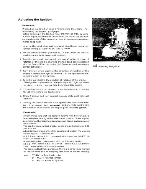
For coarse adjustment purposes, there are three lines marked<br />
on the fan wheel and an integrally cast arrow on the fan housing.<br />
Mark: OT 44/1 = Top dead centre<br />
SP 44/2 = retarded ignition<br />
FP 44/3 = advanced ignition<br />
44 Adjusting the ignition