WORKSHOP MANUAL for HEINKEL TOURIST - Secret Society ...
WORKSHOP MANUAL for HEINKEL TOURIST - Secret Society ...
WORKSHOP MANUAL for HEINKEL TOURIST - Secret Society ...

Create successful ePaper yourself
Turn your PDF publications into a flip-book with our unique Google optimized e-Paper software.
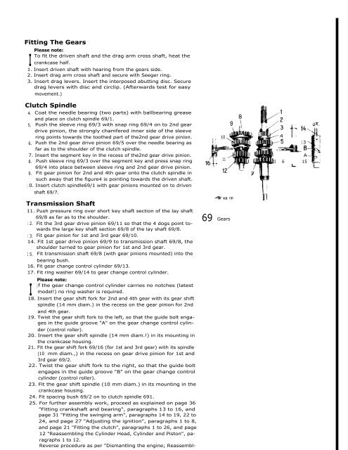
Fitting The Gears<br />
I Please<br />
note:<br />
To fit the driven shaft and the drag arm cross shaft, heat the<br />
crankcase half.<br />
1. Insert driven shaft with hearing from the gears side.<br />
2. Insert drag arm cross shaft and secure with Seeger ring.<br />
3. Insert drag levers. Insert the interposed abutting disc. Secure<br />
drag levers with disc and circlip. (Afterwards test <strong>for</strong> easy<br />
movement.)<br />
Clutch Spindle<br />
4. Coat the needle bearing (two parts) with ballbearing grease<br />
and place on clutch spindle 69/1.<br />
5. Push the sleeve ring 69/3 with snap ring 69/4 on to 2nd gear<br />
drive pinion, the strongly chamfered inner side of the sleeve<br />
ring points towards the toothed part of the2nd gear drive pinion.<br />
6. Push the 2nd gear drive pinion 69/5 over the needle bearing as<br />
far as to the shoulder of the clutch spindle.<br />
7. Insert the segment key in the recess of the2nd gear drive pinion.<br />
8. Push sleeve ring 69/3 over the segment key and press snap ring<br />
69/4 into place between sleeve ring and 2nd gear drive pinion.<br />
9. Fit gear pinion <strong>for</strong> 2nd and 4th gear onto the clutch spindle in<br />
such away that the figure4 is pointing towards the driven shaft.<br />
1 0. Insert clutch spindle69/1 with gear pinions mounted on to driven<br />
shaft 69/7.<br />
Transmission Shaft<br />
11. Push pressure ring over short key shaft section of the lay shaft<br />
69/8 as far as to the shoulder.<br />
1 2. Fit the 3rd gear drive pinion 69/11 so that the 4 dogs point towards<br />
the large key shaft section 69/8 of the lay shaft 69/8.<br />
1 3. Fit gear pinion <strong>for</strong> 1st and 3rd gear 69/10.<br />
14. Fit 1st gear drive pinion 69/9 to transmission shaft 69/8, the<br />
shoulder turned to gear pinion <strong>for</strong> 1st and 3rd gear.<br />
1 5. Fit transmission shaft 69/8 (with gear pinions mounted) into the<br />
bearing bush.<br />
16. Fit gear change control cylinder 69/13.<br />
17. Fit ring washer 69/14 to gear change control cylinder.<br />
I<br />
Please note:<br />
If the gear change control cylinder carries no notches (latest<br />
model!) no ring washer is required.<br />
18. Insert the gear shift <strong>for</strong>k <strong>for</strong> 2nd and 4th gear with its gear shift<br />
spindle (14 mm diam.) in the recess on the gear pinion <strong>for</strong> 2nd<br />
and 4th gear.<br />
19. Twist the gear shift <strong>for</strong>k to the left, so that the guide bolt engages<br />
in the guide groove "A" on the gear change control cylin-<br />
der (control roller).<br />
20. Insert the gear shift spindle (14 mm diam.!) in its mounting in<br />
the crankcase housing.<br />
21. Fit the gear shift <strong>for</strong>k 69/16 (<strong>for</strong> 1st and 3rd gear) with its spindle<br />
(10 mm diam.,) in the recess on gear drive pinion <strong>for</strong> 1st and<br />
3rd gear 69/2.<br />
22. Twist the gear shift <strong>for</strong>k to the right, so that the guide bolt<br />
engages in the guide groove "B" on the gear change control<br />
cylinder (control roller).<br />
23. Fit the gear shift spindle (10 mm diam.) in its mounting in the<br />
crankcase housing.<br />
24. Fit spacing bush 69/2 on to clutch spindle 691.<br />
25. For further assembly work, proceed as explained on page 36<br />
"Fitting crankshaft and bearing", paragraphs 13 to 16, and<br />
page 31 "Fitting the swinging arm", paragraphs 14 to 19, 22 to<br />
24, and page 27 "Adjusting the ignition", paragraphs 1 to 8,<br />
and page 21 "Fitting the clutch", paragraphs 1 to 26, and page<br />
12 "Reassembling the Cylinder Head, Cylinder and Piston", paragraphs<br />
1 to 12.<br />
Reverse procedure as per "Dismantling the engine; Reassembl-<br />
10<br />
11<br />
69 Gears<br />
4<br />
1 3<br />
A<br />
JI 6 15