Script for Laboratory: Designing embedded ASIPs - CES
Script for Laboratory: Designing embedded ASIPs - CES
Script for Laboratory: Designing embedded ASIPs - CES

Create successful ePaper yourself
Turn your PDF publications into a flip-book with our unique Google optimized e-Paper software.
<strong>Laboratory</strong>: “<strong>Designing</strong> Application<br />
Specific Embedded Processors”<br />
This work uses ASIP Meister developed by PEAS Project, Osaka University.<br />
11/8/2006
Table of contents<br />
1 Introduction.......................................................................4<br />
1.1 Application specific instruction set processors.............................4<br />
1.2 Goal of the laboratory...................................................................5<br />
2 Working Environment .....................................................6<br />
2.1 Network structure .........................................................................6<br />
2.2 Basic UNIX Commands/Programs...............................................6<br />
2.3 Directory Structure .....................................................................11<br />
2.4 Text editors.................................................................................16<br />
3 Dlxsim ..............................................................................17<br />
3.1 The DLX architecture.................................................................17<br />
3.2 Extending dlxsim........................................................................22<br />
3.2.1 Configuring dlxsim.......................................................................................................22<br />
3.2.2 How to add a new instruction .......................................................................................24<br />
3.2.3 How to add a new instruction-<strong>for</strong>mat ...........................................................................25<br />
3.3 Using dlxsim...............................................................................26<br />
3.3.1 Statistics........................................................................................................................28<br />
3.3.2 Debugging with dlxsim ................................................................................................29<br />
4 ASIP Meister ...................................................................32<br />
4.1 Typical challenges while working with ASIP Meister ...............32<br />
4.2 Typical Error Messages and their solutions................................33<br />
4.3 Tutorial <strong>for</strong> the “Flexible Hardware Model” (FHM)..................35<br />
4.4 Multi cycle FHMs ......................................................................40<br />
4.5 General hints about FHMs..........................................................43<br />
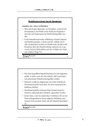
5 ModelSim.........................................................................45<br />
5.1 Tutorial.......................................................................................45<br />
5.1.1 Create a new ModelSim Project ...................................................................................45<br />
5.1.2 Include the testbench and ASIP Meister CPU files ......................................................46<br />
5.1.3 Compile the project ......................................................................................................47<br />
5.1.4 Run the simulation........................................................................................................48<br />
5.1.5 Statistics of the simulation............................................................................................50<br />
5.2 General hints...............................................................................52<br />
- 2 -
6 Validating the CPU in Prototyping Hardware.............54<br />
6.1 Creating the ISE Project .............................................................54<br />
6.2 Synthesizing and implementing the ISE project.........................57<br />
6.3 Initializing the software and uploading to the prototyping<br />
board...........................................................................................58<br />
6.3.1 Hardware specific limitations of the application ..........................................................60<br />
6.4 Getting the accurate area and delay reports ................................60<br />
6.5 Getting the critical path report....................................................62<br />
7 Power estimation.............................................................65<br />
7.1 Different types of power.............................................................65<br />
7.2 Estimating the power consumption ............................................66<br />
7.2.1 Generate the value change dump file using ModelSim ................................................66<br />
7.2.2 Generating the power report using xPower ..................................................................67<br />
7.2.3 Visualize the power report using CosmosScope...........................................................68<br />
8 CoSy compiler .................................................................69<br />
8.1 Basics about retargetable compilers ...........................................69<br />
8.2 Creating the CoSy compiler .......................................................70<br />
8.2.1 Structure of a CoSy rule ...............................................................................................71<br />
8.2.2 Typical problems while creating the CoSy compiler....................................................72<br />
8.3 Using the CoSy compiler............................................................73<br />
8.3.1 Typical reasons why a special instruction is not automatically used............................75<br />
8.3.2 Typical problems while using the CoSy compiler........................................................76<br />
8.4 Support <strong>for</strong> Inline Assembly (SINAS) .......................................76<br />
8.5 Library with standard functions <strong>for</strong> ASIP Meister / CoSy /<br />
Hardware Prototype....................................................................80<br />
8.5.1 Functions of the LCD library........................................................................................81<br />
9 Custom instruction identification..................................84<br />
9.1 What is a custom instruction ......................................................84<br />
9.2 Speedup calculation....................................................................86<br />
9.3 How to use gprof ........................................................................88<br />
Table of Figures..............................................................................89<br />
References.......................................................................................91<br />
- 3 -
1 Introduction<br />
This document was written <strong>for</strong> the participants of the students laboratory “Developing<br />
Embedded Application Specific Processors”, that is given at the Chair<br />
<strong>for</strong> Embedded Systems [<strong>CES</strong>] at the University of Karlsruhe. This document assumes<br />
a tool and environment setup specific to this laboratory. Many parts<br />
were written with our development environment in mind and cannot be applied<br />
to other setups without change, but users of such setups can get an impression<br />
about the tool chains <strong>for</strong> specific tasks.<br />
1.1 Application specific instruction set processors<br />
Application Specific Instruction-set Processors (<strong>ASIPs</strong>) are a good trade-off between<br />
Application Specific Integrated Circuits (ASICs) and General Purpose Processors (GPPs).<br />
ASICs show the best per<strong>for</strong>mance in energy and speed, but on the other hand, they have the<br />
highest development costs and there<strong>for</strong>e are only reasonable <strong>for</strong> high volume products. Unlike<br />
ASICs, where everything is executed in hardware, GPPs execute everything in software. This<br />
makes them extremely flexible, but on the other hand, they show a bad per<strong>for</strong>mance in energy<br />
and speed terms, especially compared to ASICs.<br />
<strong>ASIPs</strong> are processors with an application specific instruction set. So in contrast to the GPPs<br />
they are optimized <strong>for</strong> a specific application or <strong>for</strong> a group of applications. For this group of<br />
applications they achieve better energy and speed results than GPPs, as they have hardware<br />
support <strong>for</strong> these applications. However, contrary to ASICs they are still very flexible and can<br />
execute any kind of application, although they do not have the energy and speed benefits <strong>for</strong><br />
other applications. The customization of <strong>ASIPs</strong> typically addresses three architectural levels<br />
that vary depending on the plat<strong>for</strong>m vendor [Henkel03]:<br />
• Instruction extension. The designer can define customized instructions by specifying their<br />
functionality. The extensible processor plat<strong>for</strong>m will then generate the extended instructions<br />
that then coexist with the base instruction set.<br />
• Inclusion/exclusion of predefined blocks. The designers can choose to include or exclude<br />
predefined blocks as part of the extensible processor plat<strong>for</strong>m. Block examples include<br />
special function registers, built-in self-test, multiply-and-accumulate operation blocks, and<br />
caches.<br />
• Parameterization. The designer can fix extensible processor parameters such as instruction<br />
and data cache sizes, the number of registers, and so on.<br />
- 4 -
Figure 1-1<br />
GPPs, <strong>ASIPs</strong> and ASICs [Henkel06]<br />
<strong>ASIPs</strong> represent a good trade-off between Application Specific Integrated Circuits (ASICs)<br />
and General Purpose Processors (GPPs), as shown in Figure 1-1. ASICs have the highest<br />
efficiency due to the fact, that they are often manually optimized <strong>for</strong> a specific task and<br />
there<strong>for</strong>e no unnecessary elements are included. This has a high impact to the power consumption<br />
and the execution speed, but it causes a high time-to-market and high development<br />
costs. Nevertheless, these development costs can amortize when selling a huge amount of<br />
units, due to the lower costs per unit. The GPPs are less efficient due to the fact, that they are<br />
usable <strong>for</strong> many different kinds of applications and there<strong>for</strong>e often contain blocks that are not<br />
needed <strong>for</strong> a certain task. Whenever an application domain changes frequently due to e.g.<br />
changing standards, then the GPPs are capable to adapt to these changes, whereas the ASIC<br />
would need to be redesigned.<br />
1.2 Goal of the laboratory<br />
This laboratory shall teach the creation of <strong>ASIPs</strong> from the design, over the high-level<br />
simulation to the final prototype on FPGA hardware. Benchmarks of speed, needed area and<br />
power/energy consumption shall be per<strong>for</strong>med and compared among different created <strong>ASIPs</strong>.<br />
For this purpose the usage of the different tools have to be practiced and the connection of<br />
those tools to <strong>for</strong>m a tool chain has to be understood.<br />
The main goal is creating new <strong>ASIPs</strong> <strong>for</strong> special applications, to benchmark those <strong>ASIPs</strong> to<br />
find out their benefits and drawbacks and finally to interpret the benchmark results.<br />
- 5 -
2 Working Environment<br />
This chapter explains the technical environment <strong>for</strong> the laboratory. This includes<br />
the usage of the computers and the directory structure <strong>for</strong> this laboratory.<br />
It is very important to understand completely the directory structure, as<br />
many scripts rely on this special structure and will not work at all or create an<br />
unexpected output if the directory structure set up in a wrong way.<br />
2.1 Network structure<br />
You will work with the workstations in room 268. The programs needed to solve the tasks<br />
will run under Linux. There<strong>for</strong>e, you have to use SuSE Linux, which is installed via Dual-<br />
Boot (SuSE Linux / Windows XP) on every workstation. For certain tasks it will be necessary<br />
to change the machine in order to meet the requirements of computing power.<br />
There is one dedicated application workstations:<br />
• i80pc06.ira.uka.de – CoSy Compiler system:<br />
You will use this PC <strong>for</strong> building your own customized compiler that is able to use the<br />
instructions you added to the instruction set of the basic processor. This task also<br />
needs a powerful machine to complete in a reasonable amount of time.<br />
In most cases you don’t have to manually login into those machines or to copy data to or from<br />
those machines. We will provide scripts that will do the work <strong>for</strong> you. Just be aware of the<br />
fact that it will sometimes take time to complete everything. If some errors will occur, try to<br />
find out what is wrong by reading the script output carefully. That will show what went<br />
wrong. Start again or if it fails, again ask your tutor. The most important thing is to know or<br />
to recognize that the results of the script task are right or wrong. That depends on the output,<br />
so read it carefully be<strong>for</strong>e starting the next task.<br />
The lab program directory is mounted via NFS to your client. Thus, almost every program<br />
will work on your local machine. Data supplied to the groups or created by them will be<br />
stored on a server directory that is always available <strong>for</strong> a client machine. All client machines<br />
are configured as NFS clients, which mount the corresponding home directory via NFS. This<br />
means you can work wherever you want. The hostname will change, but when you list your<br />
home directory, you will always see the same contents.<br />
To switch between the machines mentioned above you have to use SSH. The names of the<br />
client PCs are similar to i80pcXX.ira.uka.de with the ‘XX’ replaced by the individual number<br />
of the PC. Login with SSH requires authentication, which can be done with passwords or<br />
public keys. In order to minimize the ef<strong>for</strong>ts <strong>for</strong> changing machines we recommend public<br />
keys, so you do not have to type your password <strong>for</strong> every remote login.<br />
2.2 Basic UNIX Commands/Programs<br />
If you are familiar with the Unix/Linux environment, you can skip this section.<br />
In this section, “Unix” will refer to GNU/Linux mostly.<br />
- 6 -
• Command line interpreter<br />
Interaction with the system usually is done via the command line, although some file<br />
system operation can be done with graphical or text based file managers.<br />
The command line interpreter (generally called “shell”) runs on a terminal and primarily<br />
provides the user with the means to start programs. It also has several built in<br />
commands as well as a scripting language. The default shell in the lab is bash<br />
(Bourne Again Shell).<br />
Some programs and commands require command line arguments (parameters), which<br />
can be supplied in a space-separated list to the program, i.e.:<br />
cp file1 file2 executes the program “cp” with the arguments “file1” and<br />
“file2”.<br />
• Online help system: Most UNIX commands come with documentation in the manual<br />
page <strong>for</strong>mat (man pages). They usually give a detailed description of the program, all<br />
command line parameters and some examples. Use the man command to read manpages,<br />
i.e.: man ls calls up the man page <strong>for</strong> the “ls” command. Use the up and<br />
down arrow keys (or Page Up/Down) to navigate in the man page viewer and “q” to<br />
quit.<br />
• Interacting with the file system<br />
a. File system structure: UNIX organizes all files (regular and special files) in a tree<br />
structure. The root of the tree is called “/”, directories are the nodes (leaf or nonleaf)<br />
and files the leaf nodes of the tree. The file system does not have a concept of<br />
drives – new data from external media (networked or removable) is accessed by<br />
attaching the sub tree of the new file system to the UNIX file system tree somewhere.<br />
Usually ordinary users are not permitted to do this.<br />
b. Working directory: Every process has a current working directory – a pointer to a<br />
directory node in the file system tree. The current working directory is referred to<br />
as “.”. The parent directory is “..”. To print the current working directory of the<br />
shell, use the command “pwd” (print working directory).<br />
c. Home directory: Every user has a home directory – one of the few he has write access<br />
to. All your data will be saved in subdirectories of your home directory.<br />
Home directories are mounted via NFS from a remote server. Home directories<br />
have the <strong>for</strong>m of /home/asip01 but a user can refer to his home directory with<br />
~. Hence, /home/asip01/test and ~/test (executed by asip01) refer to the<br />
same.<br />
d. File Paths: To specify a file or a directory, a path name must be provided. There<br />
are two kinds of paths: absolute and relative. An absolute path starts at the root directory,<br />
a relative path starts at the current working directory. File system nodes<br />
(path name components) are separated by “/” (the same as the backslash in Windows).<br />
A relative path may be: ./ASIPMeisterProjects/dlx_basis<br />
which refers to the file or directory “dlx_basis” of the subdirectory ASIPMeister-<br />
- 7 -
Projects of the current working directory. An example <strong>for</strong> an absolute path is<br />
/home/asip01/test.<br />
e. Changing the current working directory: To change the current working directory<br />
use the cd command with a path name as the argument, i.e.:<br />
i. cd /home/asip01<br />
ii. cd ..<br />
iii. cd ../asip02/ASIPMeisterProjects<br />
iv. cd ./dlx_basis/Applications<br />
f. Creating/Removing directories: the mkdir command takes a pathname as an argument<br />
and creates a new directory accessible via this path. The “-p” parameter<br />
tells mkdir to create any missing subdirectories as well. “rmdir” deletes empty<br />
directories. To remove non-empty directories use the “rm” command with the<br />
“-r” option (see below). Examples:<br />
i. mkdir ~/ASIPMeisterProjects/dlx_basis/Applications<br />
ii. rmdir ../dlx_basis/test1<br />
iii. mkdir –p ~/some/non_existing/directory<br />
g. Listing directory contents: To examine directory contents use the ls command.<br />
Without parameters, it will show the file and directory names of the current working<br />
directory. The ls command has many parameters, all described in the man<br />
page. Typical ones are “-l” to provide a detailed listing, “-a” to show hidden<br />
files (filenames starting with a “.”), “-ltc” give a detailed listing with the last<br />
file modification time and sort by it (actually these are three parameters). Examples:<br />
i. ls<br />
ii. ls –l ../ASIPMeisterProjects<br />
iii. ls –ltc ASIPMeisterProjects/dlx_basis/ModelSim<br />
h. Moving and removing files: To move or rename a file use the mv command with<br />
the filename or directory as the argument. To remove a file use rm; the “-r” option<br />
causes recursive removal of subdirectories and their contents. Examples:<br />
i. mv Applications/tset Applications/test<br />
ii. rm /home/asip01/oldfile<br />
iii. rm –r ../dlx_basis<br />
- 8 -
i. Copying files: the cp command copies files and directories. Its arguments are: optional<br />
switches, then the source and the target. The “-r” switch enables recursive<br />
copying. Examples:<br />
i. cp TestData.IM TestData.IM-backup<br />
ii. cp –r dlx_basis dlx_custom<br />
• Shell operation:<br />
a. Input/Output redirection: Some programs read data on their standard input file descriptor<br />
(stdin), some write output to the standard output (stdout). Usually stdin is<br />
linked to the keyboard and stdout to the terminal screen. However, you can change<br />
this when calling a program. “someotherfile” will redirect stdout<br />
to write to “someotherfile” (if it doesn’t exist, it will be created, if it does, it will<br />
be truncated first – use “>>someotherfile” to append instead of truncate).<br />
Redirection is also possible to/from other processes via pipes: use “program1 |<br />
program2” to direct the output of program1 to the input of program2. Examples:<br />
i. ls –ltc >filelisting<br />
ii. ls | sort<br />
iii. cat >file2 (this appends the contents of file1 to file2).<br />
b. Job control: Processes started from the shell are often referred to as “jobs”. Usually,<br />
when the shell launches a program it will take control of the terminal and the<br />
shell will be suspended until the process terminates – the job “is running in the<br />
<strong>for</strong>eground”. To launch a job “in the background” – start it, but give control back<br />
to the shell immediately, append “&” to the parameter list. To list any jobs<br />
launched from this shell (they all have to be in the background), type “jobs” –<br />
this will give you the job-IDs with the program names and parameters of the jobs.<br />
To bring a job to the <strong>for</strong>eground, use “fg %job-ID” (substitute job-ID <strong>for</strong> the<br />
actual job ID). Sometimes you will want to temporarily stop a job – if the program<br />
is in the <strong>for</strong>eground, hit “CTRL-Z” (job suspension). To continue job execution in<br />
the <strong>for</strong>eground use “fg” as described above, or “bg %job-ID” to continue execution<br />
in the background.<br />
To terminate a job in the <strong>for</strong>eground, hit “CTRL-C” (send keyboard interrupt).<br />
Note that if a process is unresponsive (due to bugs – i.e. endless loop and signal<br />
processing disabled) it can ignore this; the only way to terminate it is to send a<br />
KILL signal (more on that further down).<br />
• Basic programs and commands<br />
a. Process/Activity listing. To view a complete list of running processes, use the ps<br />
program. It is mostly used with the “auxw” options to provide a complete and detailed<br />
listing. The output is usually quite long, so it is often piped into less or<br />
head.<br />
- 9 -
. Text viewer. less is a program to view text (you can use it to view binary data as<br />
well, but it regards it as a byte stream without any special <strong>for</strong>matting, except <strong>for</strong><br />
control characters – they are substituted). The argument is the file to view, otherwise<br />
data can be piped in. Once in less, use the up and down arrow keys (or Page<br />
Up/Down) to navigate, “q” to quit. To jump to a specific line (current line and byte<br />
numbers are displayed at the bottom), type the line number followed by G (i.e.<br />
123G to jump to line 123). Examples:<br />
i. less ModelSim/TestData.DM<br />
ii. ps axuw | less<br />
c. Difference between files: The diff program examines two files <strong>for</strong> differences<br />
and displays these. Useful to compare outputs of programs and see if and what<br />
changes occurred. Common options are “-u” (unified output) to have verbose<br />
output. Unified output lists the lines that were in the old file, but are not in the new<br />
file prepended with a “-“ and files that were not in the old file and are in the new<br />
file prepended with a “+”. Lines that start with neither are just context to make<br />
orientation a bit easier. File sections where changes were detected start with<br />
@@,.followed by the line ranges of the sections. Examples:<br />
i. diff –u TestData.DM-OLD TestData.DM | less<br />
d. Show only beginning/end of a file/output. The head and tail programs show<br />
only the first/last lines (respectively) of a file or data piped in. By default they<br />
show 10 lines, but the “-n x” option sets it to x lines. Tail can also monitor a file<br />
<strong>for</strong> future appends and display them (useful when watching logfiles of a running<br />
program). This is requested with the “-f” option. Examples:<br />
i. ls –ltc Applications/bubblesort | head –n 5<br />
ii. tail –n 0 –f /tmp/logfile<br />
e. Show machine activity summary: while the “ps” command gives a detailed overview<br />
of the running processes, sometimes a summary is more useful. top shows<br />
an the current number of running processes, the CPU(s), memory and swap usage<br />
and the active processes. It updates every three seconds and can be exited with<br />
“q”.<br />
• Remote operation<br />
a. Remote login. To log onto a different machine, the SSH program is available (Secure<br />
Shell). Communication between the two machines is encrypted by SSH. To<br />
simply log onto a different machine with the current user use ssh hostname. If<br />
your account username is not the same as on the local machine use<br />
ssh otheruser@hostname, where “otheruser” is the username of the account<br />
on the remote machine. SSH will ask <strong>for</strong> a password on the remote machine,<br />
and then log in and start a shell. exit will end the remote shell and terminate the<br />
ssh connection leaving you on your local machine.<br />
- 10 -
. Copying via ssh: Not all machines have NFS mounted home directories, so you<br />
will sometimes have to copy files to a remote machine. The ssh package provides<br />
scp <strong>for</strong> this, which can copy files or directories from one machine to another (if<br />
you have an account on the remote machine). The syntax is<br />
scp somefile remotehost: (note the colon at the end, omitting it will<br />
cause scp to copy “somefile” to the file “remotehost” on the local machine). To<br />
copy directory trees use scp –r directory remotehost:<br />
c. X11 <strong>for</strong>warding: GUI programs can be run on remote machines as well. Log in on<br />
a remote machine with ssh –X remotehost and start a program installed on<br />
remotehost. It will be displayed on your machine, but will operate (access files and<br />
use resources – CPU, memory, etc) on remotehost.<br />
d. Public key authentication. An alternative to providing passwords <strong>for</strong> every login is<br />
public key authentication mode. A key pair is created on your local machine and<br />
you can copy the public key to any machine you want to log on later. Once set up,<br />
authentication is done automatically and no interactive passwords are necessary.<br />
i. Create the DSA-keys:<br />
Log into any machine and invoke:<br />
ssh-keygen –t dsa<br />
Confirm the default destination <strong>for</strong> the keys. Afterwards enter your pass<br />
phrase, <strong>for</strong> example your group name or you can just leave it empty. Sometimes<br />
you will be asked <strong>for</strong> this, so remember what you entered. Public and<br />
private keys will be stored in your ~/.ssh directory.<br />
ii. Copy the public key to the remote machine:<br />
ssh-copy-id –i ~/.ssh/id_dsa.pub user@remote-machine<br />
Enter your password to confirm this step. Afterwards log out and try to log<br />
in again. This should work without having to enter the password.<br />
The complete documentation can be found in the web: http://www.schlittermann.de/ssh<br />
2.3 Directory Structure<br />
In development environments it is very useful to <strong>for</strong>ce developers to meet certain rules how<br />
program data is stored. There<strong>for</strong>e, we provide a template that makes it easier <strong>for</strong> the tutors to<br />
find the results of every group and enables us to write script files that work on fixed locations<br />
to speed up work. On the other hand, those script files depend on this directory structure. You<br />
have to completely understand and use this directory structure to avoid problems.<br />
The main directory structure is shown in Figure 2-1. Your home directory contains one<br />
special directory called “ASIPMeisterProjects”. All your ASIP Meister Projects including<br />
your applications and all other files will be placed in this directory. Inside this “ASIPMeister-<br />
Projects”-folder every project has an own subdirectory (e.g. “dlx_basis” or “AnotherProject”).<br />
We recommended that you create a new subdirectory/project <strong>for</strong> each changed CPU. Among<br />
the projects the “ASIPMeisterProjects”-folder also includes a “TEMPLATE_PROJECT”.<br />
This directory gives you an empty ASIP Meister Project, where only the script files are<br />
- 11 -
included. This template is a good starting point to create a new project from the scratch.<br />
Usually you can copy from your last project to create a new one, but sometimes it is better to<br />
start from the scratch.<br />
TEMPLATE_<br />
PROJECT TEMPLATE_<br />
PROJECT<br />
ASIPMeisterProjects<br />
dlx_basis AnotherProject<br />
dlx_basis AnotherProject<br />
dlx_basis AnotherProject<br />
Figure 2-1<br />
The directory structure <strong>for</strong> all ASIP Meister Projects<br />
The biggest part of the directory structure is placed inside each ASIP Meister project directory,<br />
e.g. “dlx_basis”, as shown in Figure 2-2. Every project directory contains three subdirectories<br />
and a set of local files. Those directories and files will be explained in the remainder<br />
of this section.<br />
The “Applications” directory contains all your user applications that you want to run and<br />
simulate on the CPU, and the scripts that are needed to support those tasks. Every application<br />
is placed inside a specific subdirectory <strong>for</strong> this application. When you want to work with the<br />
scripts, then you allays do so from this specific subdirectory. For example, you might want to<br />
work with “Application 1”, as shown in Figure 2-2. Your first step is to compile this application.<br />
Inside the “Application 1” directory, you have provided the source code “application1.c”.<br />
To compile it you have to enter the “Application 1” directory and to execute<br />
../mkimg application1.c<br />
The reference “../” to access the mkimg-script is important. The script expects to be called<br />
from the place, where the results shall be placed, so always execute the scripts from the<br />
application specific subdirectory, never from the “Applications” directory itself! The details<br />
about the parameters, the created output files and the different versions of the script<br />
(mkimg_fromS, mkall, …) are explained in Chapter 8.3. The concept of calling the scripts<br />
from the specific application subdirectory is also important <strong>for</strong> the scripts dlxsim and<br />
initMem, which are explained in Chapter 3.3 and Chapter 6.3 respectively.<br />
The scripts inside the “Applications” directory are only wrappers <strong>for</strong> the real scripts. Those<br />
wrappers first read the “env_settings” file from your project directory (e.g. “dlx_basis” in<br />
Figure 2-2). This file contains all in<strong>for</strong>mation about your current project, e.g. which compiler<br />
to use and which dlxsim to call. Afterwards the wrapper scripts call the real scripts. The real<br />
scripts are placed at a global position. This enables us to make changes to those scripts<br />
without the need to copy those changes to all your projects. The env_settings file is explained<br />
in a later paragraph of this subchapter.<br />
- 12 -
dlx_basis<br />
Applications<br />
ModelSim<br />
meister meister<br />
dlx_basis.pdb<br />
dlx_basis.pdb<br />
env_settings<br />
env_settings<br />
AssemblerTypes.inc<br />
AssemblerTypes.inc<br />
AssemblerInstructions.inc<br />
AssemblerInstructions.inc<br />
basiscc<br />
basiscc<br />
makeCosy<br />
makeCosy<br />
contCosy<br />
contCosy<br />
Application 1<br />
Application 2<br />
dlxsim<br />
dlxsim<br />
powest<br />
powest<br />
mkall(_remotePas)<br />
mkall(_remotePas)<br />
mkimg(_remotePas)<br />
mkimg(_remotePas)<br />
mkimg_fromS(_remotePas)<br />
mkimg_fromS(_remotePas)<br />
initMem<br />
initMem<br />
tb_ASIPMeister.vhd<br />
tb_ASIPMeister.vhd<br />
wave.do<br />
wave.do<br />
dlx_basis.sim<br />
dlx_basis.syn<br />
dlx_basis.sw<br />
dlx_basis.des<br />
dlx_basis.des<br />
Figure 2-2<br />
The directory structure <strong>for</strong> a specific ASIP Meister Project<br />
The “ModelSim” directory will contain your ModelSim project <strong>for</strong> simulating the CPU at<br />
VHDL level. ModelSim itself is explained in Chapter 5. It is important, that you start<br />
ModelSim inside this ModelSim directory, as it searches <strong>for</strong> specific files at the position<br />
where it was started. There are two files already placed in this directory: the test bench and a<br />
configuration <strong>for</strong> watching some CPU internal signals. The details how to use those files are<br />
explained in Chapter 5.1.<br />
- 13 -
ASIP Meister automatically creates the “meister” directory and this directory contains the<br />
ASIP Meister output, like the VHDL files. This meister directory is always created at the<br />
place, where ASIP Meister is started. So only execute ASIP Meister inside your project<br />
directory (dlx_basis in this example)! It is very important, that you always start ASIP Meister<br />
in your current project directory. Otherwise, the other scripts will not find the meister<br />
subdirectory or even worse: they work with an old version of the meister directory. The<br />
meister itself directories contains three subdirectories <strong>for</strong> the simulation VHDL files, the<br />
synthesis VHDL files and the software description respectively. Some additionally files are<br />
placed inside the meister directory itself. The most important file here is the “dlx_basis.des”<br />
file. This file contains all in<strong>for</strong>mation that are needed to create a binary file out of an assembly<br />
file, i.e. to assemble an assembly file. This file can be automatically extended with user<br />
instructions, as explained in Figure 2-3. From the subdirectories, you will mostly need the<br />
VHDL files from “dlx_basis.syn” <strong>for</strong> simulation in ModelSim as explained in Chapter 5 and<br />
<strong>for</strong> synthesis as explained in Chapter 6. Inside the “dlx_basis.sw” directory, which is needed<br />
<strong>for</strong> creating the CoSy compiler, you will mostly need the “instruction_set.arch” file, as<br />
explained in Chapter 8.2. This file contains the summary of all assembly instructions, that the<br />
compiler shall support, but sometimes this file has to be manually edited be<strong>for</strong>e starting the<br />
automatic compiler generation.<br />
Inside your project directory (“dlx_basis” in the example from Figure 2-2) are some local<br />
files that are explained in Figure 2-3. The settings <strong>for</strong> your project directory are explained in<br />
Figure 2-4.<br />
dlx_basis.pdb<br />
env_settings<br />
Filename Explanation<br />
AssemblerTypes.inc /<br />
AssemblerInstructions.inc<br />
basiscc<br />
The ASIP Meister project file, i.e. your CPU design. If you use<br />
this filename as parameter when starting ASIP Meister then the<br />
design will immediately be loaded. It is important that you<br />
always start ASIP Meister inside your current project directory,<br />
as otherwise the meister directory will be created at the wrong<br />
place, i.e. at a place where the scripts don’t expect it.<br />
This file contains all settings <strong>for</strong> your project. Every script that<br />
you call evaluates this file, so you have to take care that the<br />
in<strong>for</strong>mation in this file is correct. After you create a new project<br />
directory, your first task is to adapt this file. In the Figure 2-4 the<br />
entries in this file will be explained. The first 3 settings are the<br />
most important ones; the other settings will rarely be changed.<br />
The content of these files will be automatically added to the<br />
description file .des, which is used to explain the assembler,<br />
which instructions shall be assembled to which binary-code.<br />
Every time you call mkimg (Chapter 8.3), this extension will be<br />
per<strong>for</strong>med. With these files, you can create dummy-instruction,<br />
like mapping an instruction like NOP (which is not known to the<br />
CPU itself) to another instruction, which behaves like a NOP.<br />
The compiler binary, which is created by “makeCoSy” and which<br />
is used by “mkimg”, as explained in Chapter 8.2. The name of<br />
the compiler binary might change, but it always ends with “cc”.<br />
- 14 -
makeCoSy<br />
contCoSy<br />
Filename Explanation<br />
A script <strong>for</strong> automatically creating the CoSy compiler. The usage<br />
is explained in Chapter 8.2.<br />
A script <strong>for</strong> continuing the creation of the CoSy compiler, as<br />
explained in Chapter 8.2. In some cases, it is necessary to<br />
per<strong>for</strong>m some manual changes, if “makeCoSy” aborts with an<br />
error message. Then this script can continue the creation of the<br />
compiler after the errors have been fixed.<br />
Figure 2-3<br />
The files in a project directory<br />
Setting Explanation<br />
PROJECT_NAME = dlx_basis<br />
COMPILER_PREFIX =<br />
basisSinas<br />
DLXSIM_DIR =<br />
/usr/epp/dlxsim<br />
ASIPMEISTER_PROJECTS_<br />
DIR = ~/ASIPMeisterProjects<br />
PROJECT_DIR = ${ASIP-<br />
MEISTER_PROJECTS_DIR}/<br />
${PROJECT_NAME}<br />
CPU_NAME = dlx_basis<br />
MEISTER_DIR = ${PRO-<br />
JECT_DIR}/meister<br />
This is the name of your project directory (“dlx_basis” in<br />
Figure 2-2 or <strong>for</strong> example “AnotherProject” in Figure 2-1).<br />
Whenever you create a new project with a new directory,<br />
then you have to adapt this line.<br />
This is the prefix of the name from your compiler binary.<br />
The real compiler name gets an “cc” attached. The mkimg<br />
scripts will always use the compiler, that is specified by this<br />
line an the makeCoSy script will name the created binary as<br />
configured here. There<strong>for</strong>e, you can easy switch between<br />
different compiler versions, by just changing this line.<br />
The full directory name <strong>for</strong> the dlxsim simulator, as<br />
explained in Chapter 3.3. If you want to use a modified<br />
version of dlxsim, then you can just copy this directory into<br />
your home, make your changes and adapt this setting to use<br />
your modified version.<br />
This is the directory name <strong>for</strong> all your ASIP Meister<br />
projects, e.g. “ASIPMeisterProjects” in Figure 2-1.<br />
This is the full directory name <strong>for</strong> your current project. You<br />
don’t need to change this. The only thing you need to do is<br />
to change the settings <strong>for</strong> the project name, as mentioned<br />
above.<br />
This is the name of the ASIP Meister project file<br />
(“dlx_basis.pdb” in Figure 2-2). You do not need to change<br />
this value, as we place different ASIP Meister projects in<br />
different project directories. However, if you rename the<br />
ASIP Meister project file, then you have to change this<br />
setting too, as the directory names inside the “meister”<br />
directory depend on the name of the ASIP Meister project<br />
file.<br />
The full directory name of the “meister” subfolder. You do<br />
not have to change this value.<br />
- 15 -
Setting Explanation<br />
MODELSIM_DIR = ${PRO-<br />
JECT_DIR}/ModelSim<br />
ISE_DIR = ${PRO-<br />
JECT_DIR}ISE_Framework<br />
MKIMG_DIR =<br />
/usr/epp/mkimg<br />
COSY_DIR = /usr/epp/CoSy<br />
The full directory name of the ModelSim directory. When<br />
compiling an application, as explained in Chapter 8.3, the<br />
created binary will automatically be copied to this directory.<br />
In this directory, you can synthesize your CPU <strong>for</strong> the<br />
hardware plat<strong>for</strong>m, as explained in Chapter 6. This directory<br />
setting is used to combine the synthesis result with an<br />
application, as explained in Chapter 6.3.<br />
The full directory name <strong>for</strong> the different mkimg scripts, as<br />
explained in Chapter 8.3. You won’t need to modify this<br />
setting.<br />
The full directory name <strong>for</strong> the scripts <strong>for</strong> the CoSy<br />
compiler generation, as explained in Chapter 8.2. You<br />
won’t need to modify this setting, unless you want to use a<br />
modified version of the scripts.<br />
The name of the binary compiler. To change the name you<br />
COMPILER_NAME =<br />
can adapt the COMPILER_PREFIX setting, as explained<br />
${COMPILER_PREFIX}cc<br />
above.<br />
Figure 2-4<br />
The configurable settings <strong>for</strong> an ASIP Meister project<br />
2.4 Text editors<br />
Reference cards <strong>for</strong> vi and emacs (or just google <strong>for</strong> e.g. “emacs reference filetype:pdf” if the<br />
links are no longer valid):<br />
http://www.digilife.be/quickreferences/QRC/Vi%20Reference%20Card.pdf<br />
http://inst.eecs.berkeley.edu/~cs3/fa06/emacsreference.pdf<br />
- 16 -
3 Dlxsim<br />
Dlxsim [DLX-Package] is an instruction accurate simulator <strong>for</strong> DLX assembly<br />
code. In this laboratory, we will use a modified version of dlxsim, which is<br />
changed in such a way, that it is behaving like the ASIP Meister specific implementation<br />
of the DLX Processor, which will be created and used in the later<br />
steps of the laboratory. In the first subchapter, some basic ideas about the DLX<br />
architecture and the DLX instruction set will be introduced. Afterwards the basic<br />
usage of dlxsim will be explained. In the last subchapter, it is shown how<br />
dlxsim can be extended to support new assembly instructions, which will be<br />
added to the DLX processor with ASIP Meister.<br />
3.1 The DLX architecture<br />
The DLX architecture [Hennessy96] is designed <strong>for</strong> an easy and fast pipeline processor. It is<br />
a Load-/Store-architecture, which means that there are dedicated commands <strong>for</strong> accessing<br />
the memory and that all the other commands only work on registers, but not on memory<br />
addresses. As an implication, the DLX architecture has a big uni<strong>for</strong>m register file that<br />
consists of 32 registers with 32 bits each, where only the register r0 has a special meaning, as<br />
it is hard wired to zero. The DLX architecture also consists of registers <strong>for</strong> floating point<br />
operations, but as those operations are not supported from ASIP Meister, they will not be<br />
discussed here any further. The pipeline stages <strong>for</strong> the DLX processor are the following:<br />
1. Instruction Fetch (IF): This phase reads the command on which the program counter (PC)<br />
points from the instruction memory into the instruction register (IR) and increases the PC.<br />
2. Instruction Decode (ID): Here the instruction <strong>for</strong>mat is determined and the respectively<br />
needed parameters are prepared; e.g. reading a register from the register file or sign extending<br />
an immediate value.<br />
3. Execute (EXE): The specific operation is executed in this phase <strong>for</strong> the parameters, which<br />
have been prepared in the preceding stage.<br />
4. Memory Access (MEM): If the command is a memory access, then the access will be<br />
executed in this phase. Every non-memory access command will pass this stage without<br />
any activity.<br />
5. Write Back (WB): in the last stage, the result that has been computed or loaded will be<br />
written back to the register file.<br />
In Figure 3-1 an example <strong>for</strong> some overlapping commands in the described pipeline is shown.<br />
In the first command, the values from the registers r2 and r3 are added and the result is stored<br />
into register r1. The writeback to r1 is done in clock cycle 4, so it cannot be read earlier than<br />
in clock cycle 5. The last command of the shown pipeline example is using r1 as input and it<br />
is scheduled in such a way, that it is reading r1 in clock cycle 5, so that it is using the latest<br />
value that has just been written back by the first command. The example shows, that three<br />
successive NOPs are enough to resolve a data dependency. The DLX processor, as described<br />
- 17 -
y Hennessy and Patterson, is using a data <strong>for</strong>warding technique to resolve such data<br />
dependencies without the in-between NOPs, but ASIP Meister does not support data <strong>for</strong>warding<br />
in the current release 1.1. There<strong>for</strong>e, <strong>for</strong> ASIP Meister generated processors the NOPs are<br />
needed to resolve the data dependencies (as shown in Chapter 3.2.1 you can configure dlxsim<br />
to behave in both ways, i.e. with or without data <strong>for</strong>warding).<br />
Overlapping Overlapping Execution Execution of of multiple multiple<br />
Commands Commands with with a a data data dependency dependency<br />
r1 r1 = = r2 r2 + + r3 r3<br />
nop nop<br />
nop nop<br />
nop nop<br />
r4 r4 = = r5 r5 + + r1 r1<br />
IF IF ID ID IF IF ID EXE EXE MEM WB WB<br />
ID EXE EXE MEM WB WB<br />
IF IF ID ID IF IF ID EXE EXE MEM WB WB<br />
ID EXE EXE MEM WB WB<br />
IF IF ID ID IF IF ID EXE EXE MEM WB WB<br />
ID EXE EXE MEM WB WB<br />
IF IF ID ID IF IF ID EXE EXE MEM WB WB<br />
ID EXE EXE MEM WB WB<br />
IF IF ID ID IF IF ID EXE EXE MEM WB WB<br />
ID EXE EXE MEM WB WB<br />
Figure 3-1<br />
DLX pipeline example with a data dependency<br />
IF IF Instruction<br />
IF Instruction Fetch<br />
IF Instruction Fetch<br />
Instruction Fetch<br />
ID Fetch<br />
ID Instruction<br />
ID Instruction Decode<br />
ID Instruction Decode<br />
Instruction Decode<br />
EXE Decode<br />
EXE Execute<br />
EXE Execute<br />
EXE Execute<br />
MEM Execute<br />
MEM Memory<br />
MEM Memory Access<br />
MEM Memory Access<br />
Memory Access<br />
WB Access<br />
WB Write<br />
WB Write Back<br />
WB Write Back<br />
Write Back Back<br />
Cycle Cycle number: number: 0 0 1 1 2 2 3 3 4 4 5 5 6 6 7 7 88<br />
Under some special circumstances, less than three NOPs might be enough to resolve a data<br />
dependency. Such an example is shown in Figure 3-2. In this example, the multicycle<br />
instruction LW (Load Word) has been used and this instruction might <strong>for</strong>ce the pipeline to<br />
stall. How long the pipeline is stalled and whether it is stalled at all, relies on the speed of the<br />
used data memory. If the cache can handle a load instruction, then the pipeline might not stall<br />
at all, but if slow memory is used, then the pipeline might stall <strong>for</strong> some dozen cycles.<br />
Figure 3-3 shows how important it is to know, when exactly the pipeline is going to be<br />
stalled. The only difference between Figure 3-1 and Figure 3-2 is the order of the NOP and<br />
the LW instruction. With the LW instruction as first instruction, the stall happens just in time<br />
to resolve the data dependency. With the NOP instruction first, the stall comes too late. This<br />
shows how carefully one has to deal with pipeline stalling when manually optimizing<br />
assembly code.<br />
- 18 -
Successful<br />
Successful<br />
dissolving<br />
dissolving<br />
a<br />
a<br />
data<br />
data<br />
dependency<br />
dependency<br />
with<br />
with<br />
a<br />
a<br />
load<br />
load<br />
instruction<br />
instruction<br />
IF IF Instruction<br />
IF Instruction Fetch<br />
IF Instruction Fetch<br />
Instruction Fetch<br />
ID Fetch<br />
ID Instruction<br />
ID Instruction Decode<br />
ID Instruction Decode<br />
Instruction Decode<br />
EXE Decode<br />
EXE Execute<br />
EXE Execute<br />
EXE Execute<br />
MEM Execute<br />
MEM Memory<br />
MEM Memory Access<br />
MEM Memory Access<br />
Memory Access<br />
WB Access<br />
WB Write<br />
WB Write Back<br />
WB Write Back<br />
Write Back Back<br />
Cycle<br />
Cycle<br />
number:<br />
number:<br />
0<br />
0<br />
1<br />
1<br />
2<br />
2<br />
3<br />
3<br />
4<br />
4<br />
5<br />
5<br />
6<br />
6<br />
7<br />
7<br />
8<br />
8<br />
r1<br />
r1<br />
=<br />
=<br />
r2<br />
r2<br />
+<br />
+<br />
r3<br />
r3<br />
lw<br />
lw<br />
nop<br />
nop<br />
r4<br />
r4<br />
=<br />
=<br />
r5<br />
r5<br />
+<br />
+<br />
r1<br />
r1<br />
IF IF (stall) ID ID IF IF (stall) ID EXE EXE MEM WB WB<br />
ID EXE EXE MEM WB WB<br />
Figure 3-2<br />
Successful dissolving a data dependency with a load instruction<br />
Cycle<br />
Cycle<br />
number:<br />
number:<br />
0<br />
0<br />
1<br />
1<br />
2<br />
2<br />
3<br />
3<br />
4<br />
4<br />
5<br />
5<br />
6<br />
6<br />
7<br />
7<br />
8<br />
8<br />
r1<br />
r1<br />
=<br />
=<br />
r2<br />
r2<br />
+<br />
+<br />
r3<br />
r3<br />
nop<br />
nop<br />
lw<br />
lw<br />
Unsuccessful<br />
Unsuccessful<br />
dissolving<br />
dissolving<br />
a<br />
a<br />
data<br />
data<br />
dependency<br />
dependency<br />
with<br />
with<br />
a<br />
a<br />
load<br />
load<br />
instruction<br />
instruction<br />
r4<br />
r4<br />
=<br />
=<br />
r5<br />
r5<br />
+<br />
+<br />
r1<br />
r1<br />
IF IF ID ID IF IF ID EXE EXE MEM WB WB<br />
ID EXE EXE MEM WB WB<br />
IF IF ID ID IF IF ID EXE EXE (stall) MEM WB WB<br />
ID EXE EXE (stall) MEM WB WB<br />
IF IF ID ID IF IF ID (stall) EXE EXE MEM WB WB<br />
ID (stall) EXE EXE MEM WB WB<br />
IF IF ID ID IF IF ID EXE EXE MEM WB WB<br />
ID EXE EXE MEM WB WB<br />
IF IF ID ID IF IF ID EXE EXE MEM WB WB<br />
ID EXE EXE MEM WB WB<br />
IF IF Instruction<br />
IF Instruction Fetch<br />
IF Instruction Fetch<br />
Instruction Fetch<br />
ID Fetch<br />
ID Instruction<br />
ID Instruction Decode<br />
ID Instruction Decode<br />
Instruction Decode<br />
EXE Decode<br />
EXE Execute<br />
EXE Execute<br />
EXE Execute<br />
MEM Execute<br />
MEM Memory<br />
MEM Memory Access<br />
MEM Memory Access<br />
Memory Access<br />
WB Access<br />
WB Write<br />
WB Write Back<br />
WB Write Back<br />
Write Back Back<br />
IF IF ID ID IF IF ID EXE (stall) MEM WB WB<br />
ID EXE (stall) MEM WB WB<br />
IF IF ID ID IF IF ID (stall) EXE MEM WB WB<br />
ID (stall) EXE MEM WB WB<br />
Figure 3-3<br />
Unsuccessful dissolving a data dependency with a load instruction<br />
- 19 -
The instruction set of the DLX architecture is separated into 4 instruction classes (arithmetic<br />
<strong>for</strong> integer, arithmetic <strong>for</strong> float, load/store and branch), which are implemented in 3<br />
instruction <strong>for</strong>mats, as shown in Figure 3-4. The arithmetic instructions use either an<br />
instruction <strong>for</strong>mat <strong>for</strong> three registers or an instruction <strong>for</strong>mat <strong>for</strong> two registers and an immediate<br />
value. The load/store instructions always use the <strong>for</strong>mat with two registers and one<br />
immediate, where the effective address is compute as the sum of one register (as base address)<br />
and the immediate. The other register is used either as value to store or as register where to<br />
save the loaded value. The branch instructions are divided into conditional branches and<br />
unconditional jumps. The jumps always use an instruction <strong>for</strong>mat with a 26-bit immediate, so<br />
they have a big PC-relative jump-target. The conditional branches need a field <strong>for</strong> a register<br />
that contains the condition, so they restrict to a 16-bit immediate. The second available<br />
register in the <strong>for</strong>mat <strong>for</strong> branches is not used by the branch instructions.<br />
Instruction-<strong>for</strong>mats<br />
Instruction-<strong>for</strong>mats<br />
Instruction-classes<br />
Instruction-classes<br />
6 5 5 5 11<br />
6 5 5 5 11<br />
R-Format: Opcode rs1 rs2 rd func<br />
R-Format: Opcode rs1 rs2 rd func<br />
6 5 5 16<br />
6 5 5 16<br />
I-Format: Opcode rs1 rd Immediate<br />
I-Format: Opcode rs1 rd Immediate<br />
6 26<br />
6 26<br />
J-Format: Opcode Offset<br />
J-Format: Opcode Offset<br />
Arithmetic Arithmetic instructions<br />
Arithmetic instructions <strong>for</strong><br />
Arithmetic instructions <strong>for</strong> integers<br />
instructions <strong>for</strong> integers<br />
<strong>for</strong> integers integers<br />
Arithmetic Arithmetic instructions<br />
Arithmetic instructions <strong>for</strong><br />
Arithmetic instructions <strong>for</strong> floating<br />
instructions <strong>for</strong> floating points<br />
<strong>for</strong> floating points<br />
floating points points<br />
Load Load and<br />
Load and store<br />
Load and store instructions<br />
and store instructions<br />
store instructions instructions<br />
Branch Branch instructions<br />
Branch instructions<br />
Branch instructions instructions<br />
Figure 3-4<br />
Instruction <strong>for</strong>mats and classes of the DLX architecture<br />
For many assembly-commands, there are special versions <strong>for</strong> dealing with unsigned values<br />
and <strong>for</strong> using immediate values as seconds input parameters. Those versions have an attached<br />
“i” <strong>for</strong> “immediate” and/or an attached “u” <strong>for</strong> “unsigned” as suffix (e.g. addui). A summary<br />
of all assembly instructions that are available in the ASIP Meister specific implementation of<br />
the DLX processor that is used in the laboratory (i.e. dlx_basis) is shown in Figure 3-5. For a<br />
more detailed description of the assembly-commands have a look into [Sailer96].<br />
- 20 -
Instruction Description Instruction Description<br />
add, addu,<br />
addi, addui<br />
Add; Syntax: add rd rs0<br />
rs1; rs1 can alternatively be<br />
the immediate<br />
sub, subu,<br />
subi, subui Subtract<br />
mult, multu Multiply div, divu Divide<br />
mod, modu Modulo and, andi And<br />
or, ori Or xor, xori Xor<br />
sll, slli Shift left logical srl, srli Shift right logical<br />
Set “less than”; Syntax: slt<br />
sra, srai Shift right arithmetic<br />
slt, sltu,<br />
slti<br />
rd rs0 rs1; Compare rs0<br />
and rs1 and set rd to 1 if and<br />
only if rs0 is “less than” rs1<br />
sgt, sgtu,<br />
sgti<br />
Set “greater than”<br />
sle, slue,<br />
slei<br />
Set “less or equal”<br />
sge, sgeu,<br />
sgei<br />
Set “greater or eaqual” seq, seqi Set “equal”<br />
Load high immediate; Syntax:<br />
lhi rd imm; Load an 16-bit<br />
sne, snei Set “not equal” lhi<br />
immediate into the 16 high<br />
bits of an register; use together<br />
with “ori” to load an 32-bit<br />
immediate<br />
lb, lbu Load Byte lh, lhu Load High<br />
lw<br />
Load Word; Syntax: load<br />
rd, imm(rs); the effective<br />
address is computed by<br />
adding the immediate to rs<br />
sb<br />
Store Byte; Syntax: store<br />
imm(rd), rs; the effective<br />
address is computed by adding<br />
the immediate to rd<br />
sh Store High<br />
Branch if “equal zero”<br />
Syntax: branch rs, imm;<br />
sw Store Word<br />
beqz the branch target is a PCrelative<br />
address, given by the<br />
immediate<br />
bnez Branch if “not equal zero”<br />
Jump (register); Syntax: j<br />
Jump and link (register);<br />
imm; jr rs; The jump target<br />
Similar to j/jr, but also writes<br />
j, jr is a PC-relative address, given jal, jalr the address from the following<br />
by the immediate or the<br />
command to the link register;<br />
register<br />
Figure 3-5<br />
used <strong>for</strong> subroutines<br />
Summary of all assembly instructions in the dlx_basis processor<br />
- 21 -
Finally, some specialties in the architecture need to be mentioned:<br />
• Delay slots: An instruction, that is placed right after an unconditional jump or a conditional<br />
branch instruction is always executed. In fact, there are two instructions, that enter<br />
the pipeline, but only the first one is executed, the second one will not be allowed to write<br />
the computed result back to the register file.<br />
• Multicycle operations: The operations mult, div and mod in their different versions are<br />
multicylce operations. That means, that those operations will not stay <strong>for</strong> one cycle in the<br />
execute phase, but <strong>for</strong> multiple cycles. The pipelined is stalled until the instructions finished<br />
their work in the execute stage.<br />
• Stalling: The communication to the data memory is controlled by Request/Acknowledge-<br />
Signals to deal with memories of different speed. The corresponding assembly instructions<br />
might stay <strong>for</strong> multiple cycles in the memory stages, until the memory access is<br />
finished.<br />
• Special Registers: Some registers in the general-purpose register file usually handle some<br />
special cases. However, contrary to the hard-wired zero-register r0 any register, as long it<br />
is done consistent in the assembly file, can handle those other special cases. Those special<br />
cases are the stack pointer (r29), the frame pointer (r30) and the link register (r31), which<br />
is then used as return address.<br />
3.2 Extending dlxsim<br />
3.2.1 Configuring dlxsim<br />
Some parameters can be adapted when starting dlxsim. All mentioned parameters in<br />
Figure 3-6 do not allow blanks between a parameter and a possible value, e.g. “-pd1” instead<br />
of “-pd 1”.<br />
-ms#<br />
(Memory Size)<br />
-ffilename<br />
Option Description<br />
-da#<br />
(Debug Assembly)<br />
The size of the memory that is available within dlxsim. It is the<br />
common memory <strong>for</strong> instructions and data.<br />
This parameter will load an assembly file after initialization. This<br />
parameter is equivalent to the instruction “load {filename}” in<br />
Figure 3-8.<br />
This option helps you debugging the simulated assembly code. A<br />
debugging output is printed <strong>for</strong> all load/store and jump/branch<br />
instructions, including in which cycle the message was printed and<br />
from which address it was triggered. By default, this option is turned<br />
on. To turn it off you have to enter “-da0”.<br />
- 22 -
Option Description<br />
-dbb#<br />
(Debug Base Blocks)<br />
-cdd#<br />
(Check Data Dependency)<br />
-wsdo#<br />
(Warn Specific<br />
Dependency Once)<br />
-pd#<br />
(Pipeline Delay)<br />
-pffilename<br />
This option only has an effect, if the be<strong>for</strong>e mentioned option “Debug<br />
Assembly” is enabled too. If both options are activated, then a<br />
register snapshot will automatically be printed at every base block<br />
start. This snapshot only includes registers, <strong>for</strong> which the value has<br />
changed since the last snapshot. By default, this option is turned off<br />
to avoid the enormous amount of output. To turn it on you have to<br />
enter “-dbb1”.<br />
With this option, you enable a warning message that appears when an<br />
unresolved data dependency is found in the executed assembly code.<br />
This means you will get a warning if <strong>for</strong> example, r5 is read in cycle<br />
10, but an earlier command has made a write access to r5, that cannot<br />
be read back be<strong>for</strong>e cycle 12. So you would read the ‘old’ value. By<br />
default, this option is turned on. To turn it off you have to enter<br />
-cdd0.<br />
This option belongs to the be<strong>for</strong>e mentioned option Check Data<br />
Dependency. If there is an unresolved data dependency in a loop,<br />
then the warning message would usually be printed <strong>for</strong> every time the<br />
loop is executed. With this define the warning will only be printed the<br />
first time the unresolved data dependency is noticed. By default, this<br />
option is turned on. To turn it off you have to enter –wsdo0.<br />
With this option, you can configure, whether a delayed register<br />
writeback shall be emulated and if yes, how long the delay between<br />
register write and register read shall be. The internal usage of this<br />
value is like this: If a value is written in cycle c, then it cannot be read<br />
back be<strong>for</strong>e cycle c + PipelineDelay. For the laboratory there are two<br />
useful values:<br />
With the value 1 you configure, that only the elementary delay shall<br />
be assumed. That means, that the result of an instruction can immediately<br />
be read back by the succeeding instruction. This can be<br />
imagined, like a pipeline model with a data-<strong>for</strong>warding concept.<br />
Remember, that the delay-slots <strong>for</strong> branches are still used!<br />
With the value 4 you configure the pipeline model that is used <strong>for</strong> the<br />
ASIP Meister generated processor with the register read in stage 2<br />
and the register write in stage 5. This can be imagined like a pipeline<br />
model without a data-<strong>for</strong>warding concept.<br />
Other values except 1 and 4 are basically working too, but the<br />
instructions, that imply a pipeline stall (e.g. load, mult, …) are<br />
personalized to the values 1 and 4 and might behave unexpected <strong>for</strong><br />
different values. The default value is 4.<br />
With this parameter, all print instructions (as shown in Chapter 8.5.1)<br />
are written to a file instead of the screen.<br />
Figure 3-6<br />
Summary of helpful dlxsim starting parameters<br />
Legend: cursive: replace with appropriate option<br />
#: replace with a number<br />
- 23 -
3.2.2 How to add a new instruction<br />
To add a new instruction <strong>for</strong> a given instruction-<strong>for</strong>mat is a doable task. The following list<br />
shows you the needed steps. The given line numbers are rounded and might change during<br />
time, as the source code is partially under development. Every needed part of the source code<br />
is marked with a comment that includes the string “ASIP NEW_INSTRUCTIONS”.<br />
1. dlx.h:235 Add a new define <strong>for</strong> OP_{CommandName} with a unique number.<br />
2. sim.c:365 Add the name <strong>for</strong> your assembly-command into the operationNames-array.<br />
The position of the name in this array has to correspond with the defined<br />
number in dlx.h from the preceding step.<br />
3. asm.c:350 Add a new entry with your instruction name, instruction <strong>for</strong>mat and opcode<br />
into the opcodes-table. The instruction name should be the same like in the<br />
previous step. The already available instruction <strong>for</strong>mats are shown in<br />
Figure 3-7. There are two different possibilities <strong>for</strong> the opcode. Either you<br />
use the 6 highest bits or you use the 6 lowest bits <strong>for</strong> your opcode. The unused<br />
bits always stay 0 in the opcode field. These two possibilities differ in<br />
how dlxsim is internally handling the instruction. This will become clearer<br />
in the following step. You should use the 6 highest bits <strong>for</strong> the branch instruction<br />
<strong>for</strong>mats and the 6 lowest bits <strong>for</strong> the arithmetic instruction <strong>for</strong>mats.<br />
Have a look at the following step to find free opcodes. The following values<br />
in the opcode table are usually not that important and might be filled out by<br />
copy-and-past from a similar instruction. Only the flags are important if you<br />
use instructions with immediate values as parameter. The flags are explained<br />
in asm.c.<br />
4. sim.c:335 This step depends on your choice of the preceding step. You have used<br />
either the 6 highest bits or the 6 lowest bits <strong>for</strong> the opcode. If you have used<br />
the 6 highest bits, then you have to modify the opTable in sim.c otherwise<br />
you have to modify the specialTable. In both cases you replace the table entry<br />
at the position that corresponds to the chosen 6-bit opcode with your<br />
own OP_{CommandName}. So if you have chosen the opcode value 5, then<br />
you replace the 5 th entry (start counting with 0) in the array with your own<br />
command.<br />
5. sim.c:1350 Implement a new case <strong>for</strong> the big “switch (wordPtropcode)”-statement <strong>for</strong><br />
your command. A good start is a copy-and-paste from a similar instruction.<br />
There are 2 different variables <strong>for</strong> the parameters. For example, there is a<br />
“wordPtrrs1” and a “rs1”. In “wordPtrrs1” the number of the first<br />
source register is stored, while in “rs1” the value of this source register is<br />
stored. At the beginning of an implementation of one specific ‘case’ some<br />
macros like “LoadRegisterS1” are called. Those macros take care, that “rs1”<br />
is initialized with the current value of the register with the number<br />
“wordPtrrs1”.<br />
- 24 -
Instruction Format Parameters<br />
NO_ARGS no operands<br />
LOAD (register, address)<br />
STORE (address, register)<br />
LUI (dest, 16-bit expression)<br />
ARITH_2PARAM<br />
(dest, src) OR (dest, 16-bit immediate) OR "dest" replaced by<br />
"dest/src1"<br />
ARITH_3PARAM<br />
(dest, src1, sr2c) OR (dest/src1, src2) OR (dest, src1, 16-bit<br />
immediate) OR (dest/src1, 16-bit immediate)<br />
ARITH_4PARAM (rd, rs1, rs2, rs3) OR (rd, rs1, rs2, 5-bit immediate)<br />
BRANCH_0_OP (label) the source register is implied<br />
BRANCH_1_OP (src1, label)<br />
BRANCH_2_OP (src1, src2, label)<br />
JUMP (label) OR (src1)<br />
SRC1 (src1)<br />
LABEL (label)<br />
MOVE (dest,src1)<br />
Figure 3-7<br />
Summary of available dlxsim instruction <strong>for</strong>mats<br />
3.2.3 How to add a new instruction-<strong>for</strong>mat<br />
Adding a new instruction <strong>for</strong>mat is much more difficult than adding a new instruction <strong>for</strong> a<br />
given <strong>for</strong>mat. To add a new <strong>for</strong>mat you have to take care about how the parameters <strong>for</strong> your<br />
new <strong>for</strong>mat are to be stored in a 32-bit instruction word and how they are extracted out of it.<br />
Every needed part of the source code is marked with a comment that includes the string<br />
“ASIP NEW_FORMAT”.<br />
1. asm.c:140 Define a unique number <strong>for</strong> your instruction-<strong>for</strong>mat<br />
2. asm.c:150 Add the min and max numbers of arguments, that your instruction <strong>for</strong>mat<br />
accepts in the arrays “minArgs” and “maxArgs”. Use the position in the array,<br />
that corresponds to the defined number in the previous step.<br />
3. asm.c:765 Implement how the parameters shall be stored in the 32-bit instruction word<br />
within the “switch (insPtr->class)”-statement.<br />
4. asm.c:1080 Implement what shall be written if the instruction is disassembled in the<br />
“switch (opPtr->class)”-statement.<br />
5. sim.c:2215 In the method “compile” you have to implement how the 32-bit instruction<br />
word shall be expanded.<br />
- 25 -
3.3 Using dlxsim<br />
Dlxsim is distributed as source code, so be<strong>for</strong>e using it you have to compile it. Usually this is<br />
done, by just typing make in the tcl subfolder and afterwards in the dlxsim folder. Then you<br />
can start the program by typing dlxsim. If you want to use dlxsim <strong>for</strong> an ASIP Meister<br />
Project, then you call it by starting ../dlxsim from inside the specific application<br />
subdirectory, as shown in Chapter 2.3.<br />
Figure 3-8 shows some typical dlxsim commands. The list is not exhaustive, but it covers all<br />
the usual suspects.<br />
Command Description<br />
load filename +<br />
Load a file, parse it content and place the translated content to the<br />
simulated memory. Every address that is not mentioned in the file<br />
remains it old value.<br />
Gets a value from the simulated memory or the registers.<br />
Examples <strong>for</strong> “address” are: r0, …, r31, pc, npc (next pc), 10<br />
(memory address 10), 0x10 (memory address 16), _main (if _main is<br />
a label).<br />
Examples <strong>for</strong> “options” are: u (unsigned), d (decimal), x (hexadecimal,<br />
default), B (binary), i (instruction), v (don’t read a value, but<br />
get address {options}<br />
print the address itself; as example this can be used to translate from<br />
decimal to binary), s (interpret the upcoming sequence as 0terminated<br />
string).<br />
In the options, you can also request to get the succeeding addresses<br />
from the determined base address. As an example, “get _loop 10i”<br />
would deliver the 10 first commands from the label _loop interpreted<br />
as instruction memory. This also works, if the address is a register,<br />
e.g. get r1 5u.<br />
Places some data at the given address. The address might be a register<br />
put address data<br />
too, like in the get command.<br />
Executes the “number” next instructions. The number might be<br />
step {number} omitted; the default value is 1. The printed assembly command at the<br />
end of “step” is the next assembly command that is to be executed.<br />
Executes the assembly program, until an error occurs or a trap<br />
instruction is executed. Starts executing at “address”. If no “address”<br />
go {address} is given, then it continues executing where it stopped (e.g. after some<br />
single steps). If no instruction was executed yet, then the default<br />
address is 0.<br />
Prints some statistics about the simulated assembly program. The<br />
stats {options}<br />
options are explained in more detail in Chapter 3.3.1.<br />
quit exit Terminates the program<br />
- 26 -
Command Description<br />
stop {options}<br />
asm “command” {pc}<br />
Manages break points:<br />
“stop at address {command}”: Executes “command” whenever the<br />
given “address” is touched in any way. The default “command” is to<br />
abort the execution.<br />
“stop info”: prints the list of break points.<br />
“stop delete number + ”: deletes some specific break points. The<br />
numbers are according to the “stop info” list.<br />
Returns the opcode <strong>for</strong> “command”. If the command needs to know<br />
the address, where it is to be stored (e.g. pc-relative jumps), then the<br />
current pc can be given. Default pc is 0.<br />
Figure 3-8<br />
Summary of typical dlxsim commands<br />
Legend: cursive: replace with appropriate option<br />
{braces}: optional<br />
+ : one or multiple times<br />
Some more things have to be mentioned about dlxsim:<br />
• You can use the cursor buttons to navigate in your command history, i.e. in the previously<br />
entered commands. The left- right-arrows let you navigate inside the selected<br />
command, e.g. to correct typing errors.<br />
• When you just enter an empty command in dlxsim (i.e. just press enter without having<br />
entered a command), then the last executed command will be repeated. This is <strong>for</strong> example<br />
useful, when you want to step through your code. You just have to execute the<br />
step instruction one time manually by typing “step” in the shell and afterwards you<br />
can repeatedly press enter to execute the next step instructions.<br />
• When you press the Tabulator key, you will get an auto completion <strong>for</strong> filenames. The<br />
offered files are the files in the directory from where you started dlxsim. Although this<br />
auto completion will support the abbreviation `~` <strong>for</strong> your home directory, a load instruction<br />
with this abbreviation will fail. The same holds <strong>for</strong> loading files with the “-f”<br />
starting parameter, as shown in Figure 3-8.<br />
• After you have simulated an assembly code, you have to restart dlxsim to simulate<br />
another assembly code. The load instruction will not reset everything to its default<br />
value.<br />
• Every assembly command that accepts an immediate as parameter can also handle a<br />
label as immediate. This is especially useful <strong>for</strong> the load/store branch/jump and lhi<br />
commands.<br />
• The ASIP Meister unit <strong>for</strong> data memory access does not accept an immediate change<br />
from a load command to a store command or vice versa. Dlxsim can handle this situa-<br />
- 27 -
tion, but will print a warning to indicate, that this assembly code might produce a different<br />
result if it is simulated with the VHDL-code from an ASIP Meister CPU.<br />
3.3.1 Statistics<br />
There are lots of statistics available <strong>for</strong> the executed assembly code. You can get the statistics<br />
by typing “stats {options}”, as shown in Figure 3-8. The different available options are<br />
shown in Figure 3-9. The different options can be combined; the default option is “all”.<br />
Option Description<br />
hw Shows the memory size.<br />
stalls<br />
Shows the pipeline stalls (i.e. number of elapsed cycles, where the<br />
pipeline did not proceed) <strong>for</strong> the different categories.<br />
all<br />
Shows all be<strong>for</strong>e mentioned statistics in the same order as they appear<br />
in this figure.<br />
Resets all statistics to their initial values. This is useful if you want to<br />
reset<br />
see statistics <strong>for</strong> a specific part of the program and you want to mask<br />
the statistic results that are computed be<strong>for</strong>e you reach the beginning<br />
of this specific program part.<br />
imcount<br />
imcount2<br />
imcount3<br />
baseblocks<br />
Shows the number of executions <strong>for</strong> memory addresses. The output is<br />
organized into three columns. The first column shows how often a<br />
specific part of the instruction memory was executed. The second<br />
column shows the starting address of the specific memory part and<br />
the third column shows the size of the memory part.<br />
The different spellings of imcount (e.g. imcount2) refer to different<br />
sortings <strong>for</strong> the columns.<br />
This statistic merges neighbored memory addresses that are executed<br />
<strong>for</strong> nearly the same number into a single memory portion <strong>for</strong> which<br />
one output line is printed. The deviation to the average value is<br />
printed in the first column (e.g. “# of executions: 2 ± 1”).<br />
Shows the separation from the program into base blocks. This<br />
statistic is separated into 4 columns. The first one shows the start<br />
address and the reason why a base block starts there (e.g. a label, the<br />
command after a branch command, …). The second row shows the<br />
end address together with the reason why the base block ends there.<br />
The third row shows the size of the base block and the last row shows<br />
how often it was executed.<br />
Figure 3-9<br />
Summary of available dlxsim statistics<br />
- 28 -
3.3.2 Debugging with dlxsim<br />
This chapter assumes, that you are not only used to the assembler code and dlxsim, but that<br />
you are also used to the compiler (Chapter 8.3) and inline assembly (Chapter 8.4).<br />
General Points:<br />
• Compare the results from the CoSy compiled version and the gcc-compiled version. For<br />
the gcc compiled version you have to add printf statements <strong>for</strong> all essential variables, like:<br />
#ifndef COSY<br />
printf(“temp1: %i\n”, temp1);<br />
#endif<br />
For the CoSy-compiled version, you have to make the essential variables global, <strong>for</strong> example<br />
moving the variable “temp1” from inside the main method to a global part outside<br />
the main method. All global variables will get an own label in the assembly code with an<br />
underscore be<strong>for</strong>e the name, e.g. the variable “temp1” will get the label “_temp1”. In<br />
dlxsim you can see the value of such global variables with the “get” instruction, e.g. “get<br />
_temp1 i”.<br />
Debugging with dlxsim:<br />
• Sometimes the dlxsim simulation aborts with an error message, e.g. when a load<br />
instruction is trying to access an address that is outside the simulated memory range. In<br />
such cases, you first have to find out, which instruction is causing this crash. With the<br />
instruction “get pc” you can see the address which is currently executed. With the instruction<br />
“get {address} i” you can see which instruction is placed at this address and at which<br />
label this instruction can be found. With the instruction “get {Address}-0x10 20i” you can<br />
see the context of this instruction.<br />
• Getting more debugging in<strong>for</strong>mation from dlxsim is very helpful to understand, what the<br />
assembly code is doing. There<strong>for</strong>e, the dlxsim starting parameters “-da#” and “-dbb#” are<br />
useful. You have to replace the “#” with either a “1” to turn the option on or with a “0” to<br />
turn it off.<br />
• da#: Debug Assembly. This option is turned on by default and it will print status in<strong>for</strong>mation<br />
on the screen <strong>for</strong> every jump/branch/load/store-instruction. You can print<br />
additional status in<strong>for</strong>mation by adding your needed in<strong>for</strong>mation into the sim.c of<br />
dlxsim.<br />
• dbb#: Debug Base Blocks. When you turn on this option then at every start of a baseblock<br />
all changed register values will be printed. A base block is an elementary block<br />
of assembly code that is only executed sequentially. This means, that either all instructions<br />
of a base block are executed (one after the other) or none of them is executed at<br />
all. The borders of a base block (beginning/end) are jumps and labels. The simulation<br />
will create a huge amount of output on the screen if you turn this option on. There<strong>for</strong>e<br />
it is recommended, that you copy the output to a text file <strong>for</strong> easier reading. You can<br />
automatically print everything into a text file if you start dlxsim like:<br />
“../dlxsim -fassembly.dlxsim -dbb1 | tee output.txt”<br />
The “tee” program will copy all output to the screen and to the file.<br />
- 29 -
• Always have a look at the printed warnings when dlxsim runs the simulation. At the end<br />
of every simulation the warnings are summarized, i.e. the number of the printed warnings<br />
is shown. If the simulations aborts be<strong>for</strong>e its usual end this summary is not printed. To see<br />
the summary you can see them in the statistics with “stats warnings”.<br />
Changing the source code to find the bug:<br />
• When your CoSy compiled program is not running as expected then there are different<br />
possible steps to find the problem. First, you should try to locate which code is causing<br />
the problem. There<strong>for</strong>e, you should find a minimal C-code that still causes the problem.<br />
The further steps are much easier when the created assembly code is as small as possible.<br />
• You have to understand, what the assembly code is doing to find and understand the error.<br />
The output of a compiler is usually very difficult to read and to understand. Sometimes it<br />
is very helpful to use SINAS (Support <strong>for</strong> Inline Assembly) to make the code more readable.<br />
With SINAS, you can add your own assembler instructions or comments to the created<br />
assembly code. With SINAS, you can also <strong>for</strong>ce the compiler not to rearrange the<br />
created assembly code <strong>for</strong> optimizations. For example:<br />
asm int addComment() {<br />
@[.barrier]<br />
; COMMENT: Between the i- and the j-loop<br />
}<br />
void main() {<br />
<strong>for</strong> (int i=0; i
addComment1();<br />
functionY();<br />
addComment2();<br />
}<br />
Mighty things can be done with those macros. Another example:<br />
#define ADD_COMMENT_STRING (NUMBER, STRING) \<br />
asm void addComment ## NUMBER() { \<br />
@[.barrier] \<br />
; COMMENT: STRING \<br />
}<br />
ADD_COMMENT_STRING(3, “between X and Y”)<br />
ADD_COMMENT_STRING(4, “after Y”)<br />
void main() {<br />
functionX();<br />
addComment3();<br />
functionY();<br />
addComment4();<br />
}<br />
- 31 -
4 ASIP Meister<br />
ASIP Meister [ASIPMeister] is a development environment <strong>for</strong> creating application<br />
specific instruction set processors (<strong>ASIPs</strong>). It is not the purpose of this<br />
chapter to explain the benefits or the usage of ASIP Meister. To learn the usage<br />
of ASIP Meister you have to work through the user manual and the tutorial,<br />
which are available in the “share” subdirectory of ASIP Meister. ASIP Meister<br />
itself is located in the directory /usr/epp/ASIPmeister in our laboratory environment.<br />
The purpose of this chapter is to summarize some typical challenges<br />
with ASIP Meister and some typical but hard to understand error messages,<br />
that might appear while using the software. Chapter 4.3 will afterwards give a<br />
tutorial about the so-called ‘Flexible Hardware Model’ (FHM) of ASIP<br />
Meister, as this part is missing in the official tutorial.<br />
4.1 Typical challenges while working with ASIP Meister<br />
• The register r0 is said to be hardwired to zero in our ASIP Meister CPU. Nevertheless,<br />
this is only a hint <strong>for</strong> the compiler. The compiler will never try to write a value different<br />
from zero to this register and the compiler will use this register when a zero value is<br />
needed. However, this register can be written with any value, like all the other registers.<br />
The reason <strong>for</strong> this behavior is that the register file is created by the FHM description<br />
(flexible hardware model) in the “Resource Declaration”, and the configurations in the<br />
“Storage Specifications” are only used <strong>for</strong> the compiler and assembler, but are not used <strong>for</strong><br />
creating the hardware.<br />
• Do not use the „dlx_basis.sim“ directory, when simulating or synthesizing the VHDL<br />
code. There is a problem with the register file. Instead, use the “dlx_basis.syn” directory.<br />
This is the same VHDL-code that will be used <strong>for</strong> synthesis, as shown in Chapter 6.<br />
• ASIP Meister can only be used once on each computer. There<strong>for</strong>e, if two different groups<br />
want to work with ASIP Meister, they have to use different computers. To make sure, that<br />
ASIP Meister is at most started once on each PC, the starting script tests, whether the file<br />
“/tmp/fhm_server.log” exists in the temporary directory. ASIP Meister creates this file<br />
while starting and it is removed after ASIP Meister terminates. If this file exists, then<br />
someone else might already use ASIP Meister on the PC. However, it can also happen, that<br />
this file is not automatically deleted, after ASIP Meister terminates. If you think, that no<br />
one else is using ASIP Meister on this PC, then call a tutor to remove this file.<br />
• The ASIP Meister main GUI shows an ASIP Meister logo in the bottom-right corner. Do<br />
not click on this logo. If you click on this logo, then you will not be able to save your<br />
design anymore and you will not be able to terminate ASIP Meister. If you try, then you<br />
will the following error message: „Following windows are opened. Version in<strong>for</strong>mation“.<br />
To terminate ASIP Meister in such cases you have to execute “killall java” in a shell.<br />
- 32 -
• If you manually want to write assembly code, then you have to use the special syntax of<br />
ASIP Meister’s assembler, i.e. “pas”. Register names have to be written like “%r5”and<br />
immediate values have to be written like $42. The general structure of an assembly program<br />
is like the following:<br />
.addressing Word<br />
.section .text<br />
_main: nop<br />
...<br />
.section .data<br />
_array: .data.32 42<br />
...<br />
• At a taken jump instruction, the instruction after the jump instruction will also be executed.<br />
This is the so-called delay slot, as explained in Chapter 3.1. However, in our current<br />
implemented CPU not only the first instruction, but instead the two first instructions after a<br />
jump will enter the pipeline. The first instruction will be executed and the result will be<br />
written to the register file, while the second instruction will not be executed and nothing<br />
will be written to the register file. The reason <strong>for</strong> this behavior is, that the jump target is<br />
written to the program counter in the execute stage. At the end of the execute stage the<br />
second instruction after the jump instruction has already entered the pipeline (see<br />
Figure 3-1). Instead of flushing the pipeline, the second instruction will not be allowed to<br />
stay <strong>for</strong> multiple cycles in any of its stages and it will not be allowed to write anything to<br />
the register file.<br />
• When writing MicroOp code, be careful with macros. A macro that is defined as three<br />
stages long and started in the ID phase will execute in the ID, the EX and the MEM<br />
phases, not just in the ID phase. If you want to view an instruction’s MicroOp code without<br />
macros, select this instruction and hit the “Macro Expansion” button in the upper right<br />
corner.<br />
4.2 Typical Error Messages and their solutions<br />
Error Messages while Hardware Generation:<br />
• “Error Token: wire”: Make sure, that the organization of the MicroOp description of the<br />
pipeline stages is like the following: first, the wire definitions, then at least one blank line,<br />
then instructions without further wire declarations.<br />
• “Error Token: wire”: Make sure, that in the Instruction Definition each Instruction Format<br />
has at least one Opcode field which is set to "name", not to "binary".<br />
• „rtgen error: code 26 : dlx_basis.ppd(254)<br />
syntax error: instruction: , stage: 6, line: 255,<br />
error token: instruction.”: This message is referring to stage 6 in a 5 stage CPU. This<br />
message appears, if you have created a CPU without a reset exception in the Instruction<br />
Definition.<br />
- 33 -
Error Messages while Software Generation:<br />
• “13<br />
1 or 0 required in const value”: (the value “13” is exemplary) Make sure, that your signal<br />
assignments in the MicroOp Description contain space characters, like: “flag='0';”, with<br />
standing as a placeholder <strong>for</strong> a space character.<br />
• “The <strong>for</strong>mat of the instruction "slli" does not have all of elements. "none" is missed.”: (the<br />
instruction name “slli” is exemplary) In the Instruction Definition <strong>for</strong> an Instruction Type<br />
do not use the Field Type "Reserved" with the Field Attribute "binary".<br />
Error Messages in Hardware OR Software Generation OR anywhere else in ASIP<br />
Meister:<br />
• “Out of Memory”: Make sure, that your signal assignments in the MicroOp Description<br />
contain space characters, like: “flags="0000";”, with standing as a placeholder <strong>for</strong> a<br />
space character.<br />
• “Keyword error: "don't_care" is not name or binary”: This message can appear in the<br />
“Arch. Level Estimation”. In the Instruction Definition <strong>for</strong> an Instruction Type do not use<br />
the Field Type "Reserved" with the Field Attribute "don’t care".<br />
Error Messages outside ASIP Meister, but inside our tool chain<br />
• You have to write blanks in the MicroOp description, e.g. "result=ALU.add", with <br />
standing as a placeholder <strong>for</strong> a space character. If you write it like "result=ALU.add",<br />
meistercg will complain about something like "LU.add" (the “A” is missing in this error<br />
message), while creating the CoSy compiler.<br />
• “ERROR: IOException while reading from inputFile or writing to outputFile.<br />
"null"<br />
Aborting execution now.”: This message can appear while running the tool<br />
“ASIP_asm”, which is a part of the mkimg scripts. The reason <strong>for</strong> this message is an unusual<br />
character in the input file of ASIP_asm, i.e. the *.out file from compiler_temp. To<br />
remove this unusual sign, just open the *.out file in a text editor and copy everything into a<br />
new file. This new file should no longer contain the unusual sign. A ‘diff’ will show you<br />
the line in which the sign was placed. Now you manually have to give this modified *.out<br />
file as input to ASIP_asm to receive the TestData files. Usually this happens, if you work<br />
with hand written assembly code and the unusual sign already existed in the original assembly<br />
file. Then you better remove this sign with the described method, like <strong>for</strong> the *.out<br />
file.<br />
- 34 -
4.3 Tutorial <strong>for</strong> the “Flexible Hardware Model” (FHM)<br />
To add a new instruction to an ASIP Meister CPU one would usually write a MicroOp<br />
description <strong>for</strong> the instruction, using the facilities of an existing hardware module (ALU,<br />
shifter, adder, etc). The ability to use multiple hardware modules during one stage and to<br />
create more than one instance of a specific module combined with the operators provided by<br />
the MicroOp description language is sufficient <strong>for</strong> most basic instructions. However, this<br />
method has several shortcomings that make it impossible to do the following (among others):<br />
• Working with not program-defined wire ranges which depend on register contents or<br />
immediate values<br />
• Implementing multi-cycle instructions<br />
This tutorial will show how to write a new hardware module to provide a "rotate left"<br />
instruction.<br />
Setting up ASIP Meister<br />
In our current setup, ASIP Meister is installed globally. To modify FHMs you will need to set<br />
it up locally:<br />
1. Copy the ASIP Meister directory tree to your home directory:<br />
cp -r /usr/epp/ASIPmeister/ ~<br />
2. Update the PATH environment variable to use the local ASIP Meister directory by<br />
editing the file .bashrc.user and adding the following line at the end of the file:<br />
PATH=$HOME/ASIPmeister/bin/:$PATH<br />
3. Force the shell to re-read the rc file to use the updated PATH variable:<br />
source ~/.bashrc or logout and login again<br />
4. Verify that you are using the correct ASIP Meister copy: which ASIPmeister should<br />
print the path to the local copy<br />
5. Edit ~/ASIPmeister/bin/ASIPmeister (line 25) and make sure your local ASIP<br />
Meister path ($HOME/ASIPmeister) is assigned to the variable ASIP_MEISTER_HOME.<br />
From now on whenever relative paths (not starting with a /) are mentioned,<br />
$HOME/ASIPmeister shall be the base directory, i.e.: share/fhmdb/workdb/peas/rotator.fhm<br />
would be /home/asipXX/ASIPmeister/share/fhmdb/workdb/peas/rotator.fhm<br />
FHM structure<br />
The directory share/fhmdb has two subdirectories and the file fhmdbstruct. ASIP Meister<br />
reads this file to determine which FHM files to use. Most of the modules necessary <strong>for</strong> the<br />
basic functions of the CPU are in the directory basicfhmdb; they are further divided into the<br />
categories computational and storage. New FHMs should be added to the share/fhmdb/workdb/peas<br />
directory.<br />
- 35 -
FHMs are written in XML (eXtensible Markup Language). ASIP Meister processes their data<br />
in several stages, most importantly “HDL Generation” which creates the CPU VHDL files.<br />
Usually some <strong>embedded</strong> perl is used in the FHMs to customize VHDL code. An FHM can be<br />
divided roughly into two parts: behavior and synthesis. We are not going to differ between<br />
them, though.<br />
Header and Function description<br />
First, we need to make ASIP Meister aware of our new FHM. Edit share/fhmdb/fhmdbstruct.<br />
Go to the tag and add another model to the peas<br />
class by adding the line rotator. Save and close the file, as this is the only<br />
change needed <strong>for</strong> this file.<br />
To make your task a bit easier, we have prepared a template file with many mandatory<br />
sections already done. Copy the file share/fhmdb/workdb/peas/skeleton-1p.fhm to<br />
share/fhmdb/workdb/peas/rotator.fhm and edit this file.<br />
Name your FHM rotator by editing the name in the tag. Rename the author in<br />
the tag. The section is used to allow FHM customization from the<br />
Resource declaration section in ASIP Meister. The parameter bit_width <strong>for</strong> the input and<br />
output vector is already defined. Leave it as it is.<br />
Next, we have the function description, which is generated with an <strong>embedded</strong> perl script.<br />
Functions are used by ASIP Meister to interface the MicroOp description and the actual<br />
VHDL code. The program generates the necessary registers/multiplexers and control signals<br />
to address the according hardware module. The perl script uses the perl print function to<br />
output the function description. The
in direction;<br />
The in keyword means that the module will be able to access the signal read-only.<br />
out and inout are the other two possibilities.<br />
protocol: What the function should do once a condition is met. In this case we will use the<br />
following three lines:<br />
[direction == '0'] {<br />
valid data_out;<br />
}<br />
That is it <strong>for</strong> the function description.<br />
The function convention is next. Its syntax is similar to the description, except <strong>for</strong> the<br />
protocol block: For this block use<br />
single_cycle_protocol {<br />
direction = '0';<br />
}<br />
A small change is necessary <strong>for</strong> the control block as well, use:<br />
in bit direction;<br />
To declare additional functions, simply add their descriptions to the here document (or use a<br />
new print statement), do not start a new XML or <br />
block.<br />
Ports, Instance and Entity<br />
The section declares the signals that will be connected to our module. As<br />
with the function convention and description it is an <strong>embedded</strong> perl script, and as be<strong>for</strong>e the<br />
output is done with a here document. We mentioned all the needed ports in the function<br />
convention and description already: direction, data_in, amount, data_out. Use the following<br />
four lines <strong>for</strong> the declaration (make sure you write them between the print<br />
e used to assign values to variables. No additional signals are necessary <strong>for</strong> our rotator, so<br />
we will leave $signals as it is.<br />
The next variable, $vhdl is more interesting: Our module should be sensitive to changes of<br />
input data, shifting amount and shifting direction (so it should recompute the output data if<br />
one of these three values changes), hence we define a process with those three values in its<br />
sensitivity list. We also need one integer variable to hold the value of the shifting amount<br />
(amount is a signal, not a variable) and one signal <strong>for</strong> the temporary value of the result. After<br />
the begin keyword we can write the process code.<br />
First, we need to convert the signal amount to integer and assign it to a. Next we check if a is<br />
within range, if it isn't, we set the result to undefined, otherwise we can rotate. A case switch<br />
is used to decide into which direction to rotate. The others case is necessary, as the type<br />
std_logic has more states than just '0' and '1', so don't delete it when you add the code <strong>for</strong><br />
"rotate right".<br />
At the end of the process, we assign the value of the res signal to the data_out signal. See the<br />
below listing <strong>for</strong> the architecture VHDL:<br />
process (data_in, amount, direction)<br />
variable a : integer;<br />
variable res : std_logic_vector($msb downto 0);<br />
begin<br />
a := TO_INTEGER(UNSIGNED(amount));<br />
if (a > 0 and a < $bit_width) then<br />
case direction is<br />
when '0' => -- rotate left<br />
res($msb downto a) :=<br />
data_in($msb - a downto 0);<br />
res(a - 1 downto 0) :=<br />
data_in($msb downto $bit_width - a);<br />
when others => -- not reached<br />
res := (others => 'X');<br />
end case;<br />
else<br />
res := (others => 'X');<br />
end if;<br />
data_out
amount : in std_logic_vector(7 downto 0);<br />
data_out : out std_logic_vector($msb downto 0)<br />
That is it <strong>for</strong> the block.<br />
Next, we have an section. It defines an entity in a different file, which is why a new<br />
block is needed, but the ports are the same, so use the code from the above listing.<br />
Estimation and the Synthesis model<br />
The section can be left empty, the script contains instructions to<br />
process the FHM file - we leave that untouched as well.<br />
The block has data relevant <strong>for</strong> area, power and delay estimations, but we use<br />
more accurate tools, that consider the actual application execution, as shown in Chapter 6.4,<br />
Chapter 6.5 and Chapter 7.2. Leave the estimation data there though, as ASIP Meister will<br />
complain without them. Should you change FHM parameters however, you will have to<br />
adjust the estimation section if you want to get rid of the warnings.<br />
That is it <strong>for</strong> the behavior model. As mentioned in the beginning, we won't differ between the<br />
behavior and the synthesis model, so just copy/paste the complete block and change<br />
the value of the tag from behavior to synthesis.<br />
Your FHM file should now have a structure similar to the following listing:<br />
<br />
<br />
rotator <br />
<br />
behavior <br />
[...]<br />
<br />
<br />
synthesis <br />
[...]<br />
<br />
<br />
You can now use the module in ASIP Meister. Instantiate the FHM resource in the Resource<br />
Declaration and write the new instruction rotl. Set the operands to the correct Addressing<br />
Mode, DataType, etc in the Behavior Description window, but leave the behavior description<br />
itself out.<br />
Use the syntax<br />
result = ROT0.rotl(source0, am);<br />
where result and source0 are 32-bit wires and am is a 8-bit wire.<br />
- 39 -
Testing<br />
When HDL and SWDev Generation run without errors (SWDev will probably print some<br />
warnings about setting throughput to 1 - that is alright), proceed testing your module/instruction.<br />
Write a small assembly code, compile it (as shown in Chapter 8.3), create a<br />
new project in ModelSim, load your design and compile it. If there are errors during compilation<br />
of the VHDL files (especially in fhm_rotator_w32.vhd), then you have made a mistake in<br />
your VHDL code. Now you could go back to the FHM and correct it there, but a faster way is<br />
to edit the mentioned VHDL file in your ~/ASIPMeisterProjects/dlx_yourcpu/meister/dlx_yourcpu.syn/<br />
directory and try to correct the code there. Once you get it running, make<br />
the corrections in the FHM file as well (important: in the behavior and synthesis sections), as<br />
ASIP Meister will overwrite the VHDL files every time you recreate the CPU.<br />
Once your CPU VHDL files are compiled, run your test program. Check the results carefully!<br />
Experiment with large values as well (i.e. use lhi %r2, $65535 to set the upper 16 bits to<br />
'1'). Once you verified your design, backup your FHM (important!) and implement the rotr -<br />
right rotation instruction by making the necessary changes to your FHM.<br />
4.4 Multi cycle FHMs<br />
As mentioned at the beginning of the tutorial, one of the reasons to write custom FHMs is to<br />
implement multi-cycle (stalling) instructions. Examples of stalling instructions are the<br />
multiplication and division operations, which use dedicated multiplier and divider hardware<br />
blocks. Stalling hardware is usually implemented with State Machines. This section will show<br />
you how to write a FHM <strong>for</strong> a multi-cycle instruction. We will extend the rotator from the<br />
previous sections - the multi-cycle version will rotate only one bit per cycle (obviously the<br />
per<strong>for</strong>mance will be inferior to the single-cycle variant, it’s just <strong>for</strong> demonstration).<br />
ASIP Meister provides three signals to control multi-cycle instructions: start, fin and cancel.<br />
The start signal will be set by the RTG controller once the instruction is started, and our<br />
hardware will set the fin signal once the operation is finished, to signal the CPU that normal<br />
pipeline operation can be resumed. Should a cancel signal arrive, the hardware should abort<br />
its operation. We will disregard the cancel signal here, but reset our hardware on the CPU<br />
reset signal into its default state.<br />
<br />
We need to define the three control signals in the \texttt{control} block of our function. As<br />
the control block of your function use<br />
in start, cancel, direction;<br />
out fin;<br />
We also need a protocol <strong>for</strong> our stalling instruction. For the protocol block use:<br />
repeat [start == 1] until (fin == 1 || cancel == 1);<br />
if (fin == 1 && direction == 0) {<br />
valid data_out;<br />
}<br />
- 40 -
Add the three signals to the control block of your function. It should be now:<br />
in bit direction;<br />
in bit start;<br />
in bit cancel;<br />
out bit fin;<br />
and <strong>for</strong> the protocol block use:<br />
multi_cycle_protocol {<br />
start_signal start = '1';<br />
fin_signal fin = '1';<br />
cancel_signal cancel = '1';<br />
direction = '0';<br />
}<br />
<br />
The three signals as well as the CPU clock and reset signals need to be added to the port<br />
declaration of our FHM, so use:<br />
direction in bit mode<br />
data_in in bit_vector $msb 0 data<br />
amount in bit_vector 7 0 data<br />
data_out out bit_vector $msb 0 data<br />
clock in bit clock<br />
reset in bit reset<br />
start in bit ctrl<br />
fin out bit ctrl<br />
cancel in bit ctrl<br />
Note that the port type is ctrl, not mode <strong>for</strong> the three multi-cycle control signals, and clock<br />
and reset <strong>for</strong> the two CPU signals respectively.<br />
<br />
The VHDL implementation uses one process <strong>for</strong> the state machine, but this time we only use<br />
clock and reset in its sensitivity list. In the process body we first handle the reset case<br />
(synchronously), then depending on the current state we either start the state machine from<br />
the idle state (st0), execute a one-bit rotation (st1) or assign the result (st2). The following<br />
code is provided as text file as well:<br />
$vhdl = "process (clock, reset)<br />
type t_s is (st0, st1, st2);<br />
variable state : t_s;<br />
variable a : integer;<br />
variable res : std_logic_vector($W1 downto 0);<br />
variable tmp_data : std_logic_vector(31 downto 0);<br />
begin<br />
- 41 -
if rising_edge(clock) then<br />
-- handle reset (synchronous)<br />
if reset = '1' then<br />
state := st0;<br />
data_out 0 and a < $bit_width) then<br />
case direction is<br />
when '0' => -- rotate left one bit<br />
res($W1 downto 1) := tmp_data($W1 - 1 downto 0);<br />
res(0) := tmp_data($W1);<br />
when others => -- not reached<br />
res := (others => 'X');<br />
end case;<br />
a := a - 1;<br />
tmp_data := res;<br />
else<br />
if a /= 0 then<br />
res := (others => 'X');<br />
end if;<br />
state := st2;<br />
end if;<br />
fin <br />
data_out
data_in : in std_logic_vector($W1 downto 0);<br />
direction : in std_logic;<br />
amount : in std_logic_vector(7 downto 0);<br />
data_out : out std_logic_vector($W1 downto 0);<br />
clock : in std_logic;<br />
reset : in std_logic;<br />
start : in std_logic;<br />
cancel : in std_logic;<br />
fin : out std_logic);<br />
Again, our five signals need to be added to the entity declaration. The new entity should have:<br />
data_in : in std_logic_vector($W1 downto 0);<br />
direction : in std_logic;<br />
amount : in std_logic_vector(7 downto 0);<br />
data_out : out std_logic_vector($W1 downto 0);<br />
clock : in std_logic;<br />
reset : in std_logic;<br />
start : in std_logic;<br />
cancel : in std_logic;<br />
fin : out std_logic);<br />
Estimation, Synthesis, ASIP Meister usage and Testing<br />
No changes <strong>for</strong> estimation or synthesis but make sure to copy your changes to the behavior<br />
section of the FHM.<br />
Instantiate and use the resource in ASIP Meister just as with a singly-cycle FHM - no changes<br />
needed. Write a test program and check in ModelSim whether the pipeline actually stalls (the<br />
im_addr value shouldn't change during stalling) and whether the result is the same as with the<br />
single-cycle instruction.<br />
4.5 General hints about FHMs<br />
• Do not take the code copy and paste out of this pdf file. Often, this manifests in wrong<br />
code (e.g. wrong blanks) and the ef<strong>for</strong>t to debug the code afterwards is bigger, than manually<br />
transcribing the code.<br />
• ASIP Meister has only very few debug facilities <strong>for</strong> FHMs (e.g. /tmp/fhm_server.log<br />
contains some more in<strong>for</strong>mation compared to the popup windows). There<strong>for</strong>e, you usually<br />
have to use the trial and error scheme. The syntax <strong>for</strong> FHMs is very restrictive. Sometimes<br />
a missing blank can cause a problem. Sometimes (!) you can ignore error messages in the<br />
Resource Declaration, as long as the resource was successfully instantiated. These error<br />
messages are meant <strong>for</strong> the Estimation, which is not needed <strong>for</strong> implementation.<br />
• The exemplary FHM in this tutorial is constructed <strong>for</strong> a module with one parameter.<br />
When you need more parameters, have a look at the other existing FHMs.<br />
- 43 -
• As soon as a new FHM is successfully constructed, you can make further changes directly<br />
in the VHDL code <strong>for</strong> simplicity. Whenever the VHDL code is finalized, you should include<br />
it into the FHM file again, as the created VHDL files are overwritten every time you<br />
regenerate your CPU.<br />
• Create backups very frequently. Due to the difficult debugging, it is difficult to find and<br />
fix bugs and thus it is often simpler to go back to a slightly earlier version and to implement<br />
the changes again.<br />
- 44 -
5 ModelSim<br />
ModelSim is a full-featured VHDL simulator. With VHDL you can create logic<br />
designs consisting of any size. To verify functional operation you need to simulate<br />
your design to see whether it works like expected. There<strong>for</strong>e test benches<br />
are used. They contain so-called stimuli or test vectors, simply said: values <strong>for</strong><br />
the input signals. Those values are applied to the input signals and then the<br />
corresponding output signals are compared with the expected values.<br />
To simulate a specific design one has to provide two kinds of files to the ModelSim simulator:<br />
VHDL files that contain your processor design and a testbench file that creates the needed<br />
environment. ASIP Meister is creating the VHDL files <strong>for</strong> your processor design automatically<br />
and the designer doesn’t have to take care about the VHDL implementation of the<br />
processor. We provide the testbench and you can find it in the TEM-<br />
PLATE_PROJECT/ModelSim directory (directory structure is explained in Chapter 2.3).<br />
This testbench is providing a reset and a clock signal to the CPU. Furthermore it contains<br />
simulated data- and instruction-memory <strong>for</strong> the CPU. Those simulated memories have to be<br />
initialized with memory images that are read from TestData.DM and TestData.IM, be<strong>for</strong>e the<br />
CPU can start executing the application. The mkimg script is creating those memory images<br />
and it automatically copies them to the ModelSim directory of your current ASIP Meister<br />
project (so you are always simulating the application, that was compiled last). After the<br />
simulation of the application is finished you will find a memory image of the final data<br />
memory (TestData.OUT) that contains the results of the application if they are stored in data<br />
memory.<br />
5.1 Tutorial<br />
5.1.1 Create a new ModelSim Project<br />
Please be aware that it is important that you start ModelSim in the ModelSim directory of<br />
your ASIP Meister project, as it is shown in Chapter 2.3.<br />
On the shell change to the ModelSim directory of your project and invoke “vsim &”. If<br />
ModelSim asks <strong>for</strong> modelsim.ini choose the default.ini to proceed.<br />
Menu: File > New > Project<br />
Enter a project name and change the project location to the ModelSim directory in your<br />
project directory. Confirm the dialog with the OK button.<br />
- 45 -
Figure 5-1<br />
Creating a ModelSim Project<br />
5.1.2 Include the testbench and ASIP Meister CPU files<br />
Choose the icon Add Existing File. Browse to the meister/dlx_basis.syn directory of your<br />
ASIP Meister project. Here you will find the VHDL files <strong>for</strong> synthesis. There is also a VHDL<br />
model of the processor in the .sim directory, but don’t use the files of the .sim directory, as<br />
they don’t work properly. Mark all the files and confirm the dialog with open. Once again,<br />
choose the icon Add Existing File to add the testbench file tb_ASIPmeister.vhd in the<br />
ModelSim directory of your current project.<br />
- 46 -
5.1.3 Compile the project<br />
Figure 5-2<br />
Adding files to a ModelSim Project<br />
Menu: Compile > Compile Order > Auto Generate<br />
Every file gets compiled and you can see the result of the compile process. ModelSim<br />
determines automatically the compile order of the VHDL files. After closing the dialog every<br />
file should have a green mark behind its name, showing that the compilation was successful<br />
(instead of the question marks, shown in Figure 5-3. A green mark with a yellow dot is a<br />
warning that usually is a problem. So take care about the warnings.<br />
IMPORTANT: When you edit your CPU in ASIP Meister and execute HDL Generation, then<br />
the VHDL files are regenerated and have to be recompiled. ASIP Meister might even generate<br />
new files, that haven’t been there in the previous set of VHDL files, e.g. <strong>for</strong> new pipeline<br />
registers that are needed <strong>for</strong> modified MicroOp Descriptions. These new VHDL files are not<br />
included into your ModelSim project yet. Also previously needed VHDL files might no<br />
longer be needed <strong>for</strong> a modified ASIP Meister CPU and ModelSim will complain about these<br />
files while recompiling. To avoid manually checking every VHDL file, whether it already<br />
was included into your project or whether it is a new file, you can do the following: Delete the<br />
meister/dlx_basis.syn directory be<strong>for</strong>e executing the HDL Generation; this will make sure,<br />
that no files are existing, that are no longer needed. Remove all ASIP Meister VHDL files out<br />
of your ModelSim project and after executing the HDL Generation just add the new created<br />
VHDL files from the meister/dlx_basis.syn directory, like explained in the previous point.<br />
- 47 -
Instead of the sub window shown in Figure 5-2 when creating a new project, you can use the<br />
menu: File > Add to Project > Existing File.<br />
5.1.4 Run the simulation<br />
Menu: Simulate > Start Simulation<br />
Figure 5-3<br />
Compiling the project<br />
Open the work library, mark the entry cfg (that’s the VHDL configuration <strong>for</strong> the testbench)<br />
in the list as shown in Figure 5-4 and press OK. That will start the simulation and you will get<br />
another two tabs attached to the Workspace window (sim / Files).<br />
IMPORTANT: Make sure that no Component Unbound Message is printed while starting the<br />
simulation. If such a message is printed, then this is a serious problem within the simulation.<br />
Usually it helps to recompile everything and to start the simulation again (menu: Compile ><br />
Compile All). But a new VHDL file, that was automatically created by ASIP Meister, but that<br />
is not included into your project yet, can also cause such a message.<br />
Menu: Tools > Execute Macro<br />
- 48 -
Mark the wave.do file in your ModelSim directory and press OK to load it. The wave-window<br />
gets filled with certain signals that are useful to evaluate the simulation of the program<br />
running on the processor. Those signals are explained in Chapter 5.1.5.<br />
Figure 5-4<br />
Starting the ModelSim simulation<br />
Press the button Run all to run the simulation until it aborts. At the end of a simulation the<br />
message “Failure: Simulation End” is printed. The type “Failure” is only used to automatically<br />
abort the simulation. This is not a real failure. At the simulation end the file Test-<br />
Data.OUT is created in your ModelSim directory. It contains the content of the simulated<br />
memory after the CPU finished working. So if your algorithm is storing the result in the<br />
memory you can find the values here.<br />
If you want to run another simulation with a changed program or with a changed initial data<br />
memory, then all you have to do is to run mkimg to create the new TestData.IM and Test-<br />
Data.DM and afterwards you have to press the buttons restart and run all, like shown in<br />
Figure 5-5.<br />
- 49 -
Restart<br />
Simulation<br />
5.1.5 Statistics of the simulation<br />
Run Simulation <strong>for</strong><br />
a configurable<br />
amount of time<br />
Figure 5-5<br />
Running the ModelSim simulation<br />
Run till the end<br />
of simulation<br />
During simulation time, the testbench prints status messages about memory access<br />
(Load/Store operations) into the workspace status window. Thus, you can see which operation<br />
is being executed and which values are stored and loaded. The following examples show a<br />
read and a write access:<br />
# ClockCycle:23 InstrAddr:0x00000042 DMemAddr:0x0000FFF0 --> 0 (Read)<br />
# ClockCycle:30 InstrAddr:0x00000049 DMemAddr:0x0000FFF4
Figure 5-6<br />
ModelSim waves<br />
Signal Explanation<br />
reset The reset signal of the CPU. This signal is active at the beginning of<br />
every simulation to initialize the CPU.<br />
clk The clock signal of the CPU. This signal is helpful to see, when other<br />
signal changes are really taken into the CPU, as they are only sampled<br />
at the rising edge of the clock.<br />
clock_counter The clock counter counts the number of executed clock cycles since<br />
the CPU started running after the initial reset.<br />
im_addr This is the Instruction Memory Address. It shows the address of the<br />
instruction that the CPU wants to fetch into its pipeline.<br />
- 51 -
Signal Explanation<br />
im_data This is the Instruction Memory Data that corresponds to the previous<br />
shown im_addr. So it’s the binary representation of the assembly<br />
instruction that is fetched by the CPU.<br />
w_enb0 This is the write-enabled signal. It controls, whether the data at the<br />
input port of the register file will be written to the specified register or<br />
not. For example while jump or multicycle instructions this value is<br />
partially disabled (i.e. value ‘0’). Especially the jump instructions<br />
create a typical pattern <strong>for</strong> this signal. The jump instruction itself does<br />
not write to the register file, so this signal is ‘0’ when the jump<br />
instruction comes to its WB phase. The 2 instructions after the jump<br />
instruction enter the pipeline, but only the first one will be allowed to<br />
write its result back to the register file.<br />
w_sel0 This signal selects to which register the value at the input port of the<br />
register file shall be written.<br />
data_in0 This is the data value that is going to be written into the register file, if<br />
the write-enabled signal is active.<br />
r_selX This signal selects which register of the register file shall be read.<br />
data_outX This is the data value that was read from the requested register.<br />
dataab This is the Address Bus <strong>for</strong> memory accesses. This bus either contains<br />
the address to which some data shall be written or the address from<br />
which some data shall be read.<br />
datadb The Data Bus contains the value that shall be written or that was read.<br />
datareq This is the request signal with which the CPU triggers a read or a write<br />
access.<br />
dataack This is the acknowledge signal, that is activated by the memory<br />
controller after a requested write access is finished or after the data bus<br />
contains the result of a requested read access.<br />
datawin This signal determines the write mode. The usual values are “1111” <strong>for</strong><br />
“read word” and “0000” <strong>for</strong> “write word”, but there are also values <strong>for</strong><br />
writing 8- and 16-bit values.<br />
Figure 5-7<br />
Explanation of the signals in the ModelSim wave<br />
5.2 General hints<br />
• Change to your ModelSim directory inside your project directory tree and verify that<br />
the memory images TestData.IM and TestData.DM are present. They were build by<br />
mkimg. Furthermore you need the testbench file tb_ASIPmeister.vhd and the Model-<br />
Sim configuration script wave.do, which are available in the TEM-<br />
PLATE_PROJECT/ModelSim directory. Please check their existence in your Model-<br />
Sim directory be<strong>for</strong>e you start the work. It keeps you away from trouble.<br />
- 52 -
• Always invoke ModelSim in the specific ModelSim directory of your current project<br />
by executing vsim & in this directory. ModelSim is working with project directories<br />
and is searching <strong>for</strong> in<strong>for</strong>mation in the directory where it was started. After creating<br />
new projects all settings will be saved in the project file projectname.mpf (MPF =<br />
ModelSim Project file). To speed up the starting process you can invoke vsim with an<br />
option <strong>for</strong> your project file that you have created in an earlier simulation: ”vsim<br />
projectname.mpf &“.<br />
• When you compile VHDL files ModelSim creates a local library in the subdirectory<br />
work to store the compilation results. This is the main reason why it is important to<br />
start ModelSim in the right place. It looks <strong>for</strong> last project in<strong>for</strong>mation and <strong>for</strong> the local<br />
library.<br />
• Sometimes you might get compiler errors from the ModelSim VHDL compiler. This<br />
is usually not the fault of ASIP Meister or the testbench. Very often a recompile all<br />
solves this problem. But sometimes you will have to create a new project from the<br />
scratch to get it working.<br />
• If you open the waves be<strong>for</strong>e the simulation is started, then the signals will not be<br />
displayed. First start the simulation, and then open the waves.<br />
- 53 -
6 Validating the CPU in Prototyping Hardware<br />
In this step, we will test the CPU and application, which were generated in the<br />
previous steps, on a FPGA prototyping system. For this purpose, we will use<br />
the HW-AFX-FF1152-200 Proto Board from Xilinx shown in Figure 6-1. It<br />
contains a socket <strong>for</strong> any Virtex-II FPGA with the FF1152 Package; currently<br />
we are using an XC2V3000-6<br />
6.1 Creating the ISE Project<br />
Figure 6-1<br />
HW-AFX-FF1152-200 Prototyping Board from Xilinx<br />
ISE (also called Project Navigator) is program from Xilinx to support the whole tool-flow<br />
from managing your source files over synthesis, map, place and route to finally uploading the<br />
design to the FPGA board.<br />
If your local pc is rather slow, then you better connect to a faster pc (e.g. i80pc05) and run<br />
ISE there: ssh –X i80pcXX.<br />
Start ISE by just executing ise_8.1 &<br />
- 54 -
If you don’t already have a project <strong>for</strong> your current CPU, then create a new one: “File” –<br />
“New Project”. As Project Location you should choose your ASIP Meister Project Directory<br />
(e.g. ASIPMeisterProjects/dlx_basis/) and as Project Name you can choose something like<br />
ISE. This Project Name will then automatically be added as new subdirectory to your chosen<br />
Project Directory. In the upcoming window “Device Properties” you have to adjust the values<br />
to the data shown in Figure 6-2. Afterwards just press “Next” – “Next” – “Finish” to create an<br />
empty project <strong>for</strong> your CPU. The device settings are needed to make sure, that the map, place<br />
and route tools know exactly the type of the target FPGA.<br />
Figure 6-2<br />
ISE Device Properties<br />
Now you have to add the needed VHDL and constraint files to your ISE project, by right<br />
clicking on the xc2v3000-6ff1152 entry of your Sources View (at the upper left inside your<br />
ISE Window, see Figure 6-3) and choosing “Add Copy of Source”. After ISE has analyzed<br />
the type of the files, press OK. Adding a copy of the source has the advantage, that you can<br />
locally modify the files and that the CPU files in your ISE project are not overwritten, when<br />
you modify your ASIP Meister Project <strong>for</strong> testing purpose.<br />
There are three types of files that are needed <strong>for</strong> a hardware implementation:<br />
• CPU VHDL Files<br />
• Framework Files<br />
• IP cores<br />
- 55 -
Figure 6-3<br />
Add Sources<br />
Figure 6-4<br />
ISE project overview<br />
- 56 -
CPU VHDL Files have been generated using ASIP Meister and they can be found in the<br />
meister/{CPU-Name}.syn directory, as explained in Chapter 2.3.<br />
Framework Files are important <strong>for</strong> the connection between CPU, Memory, LCD and all<br />
other components. They are pre designed <strong>for</strong> this laboratory and they are available in<br />
~asip00/ASIPMeisterProjects/TEMPLATE_PROJECT/ISE_Framework. The framework<br />
consists of the following three types of file and all of them have to be added to the ISE<br />
project.<br />
• The VHDL files describe how all components are connected together.<br />
• The UCF file describes the user constraints (e.g. which I/O pins should be used, which<br />
clock frequency is requested).<br />
• The BMM file contains a description of the memory buildup <strong>for</strong> instruction- and datamemory<br />
<strong>for</strong> the CPU. Out of this file …_bd.bmm file will be generated while<br />
implementation and this file is then used to initialize the created bitstream with the<br />
application data, as explained in Chapter 6.3.<br />
IP cores are used within the framework, e.g. memory blocks <strong>for</strong> instruction- and datamemory<br />
or FIFOs <strong>for</strong> the connection to the LCD. These IP cores are not available as VHDL<br />
source code, but instead they are available as pre-synthesized net lists. These files just have to<br />
be available inside the directory of your ISE project (no need to actually ‘add’ them to the<br />
project) and then they will be used in the implementation step. The needed files (*.edn, *.ngc)<br />
are available in ~asip00/ASIPMeisterProjects/TEMPLATE_PROJECT/ISE_Framework.<br />
After you have added all needed files to your ISE project/directory, your main window should<br />
look similar to the screenshot shown in Figure 6-4. In the sources sub window you can see all<br />
the source files and how they are structured, i.e. which file is instantiating which other file.<br />
The other sub windows will be explained in Chapter 6.2.<br />
6.2 Synthesizing and implementing the ISE project<br />
In the Processes sub window in the lower left corner of Figure 6-4 the possible actions <strong>for</strong><br />
each kind of file is shown. To synthesize and to implement your project you have to choose<br />
your VHDL-Toplevel in the Sources sub window (“dlx_Toplevel” in the figure) and afterwards<br />
you have to double click “Generate Programming File” in the Processes sub window.<br />
This will finally create the .bit file, that can then be initialized with your CPU instruction- and<br />
data-memory and afterwards be uploaded to the FPGA prototyping board.<br />
The whole process of synthesizing and implementing the design is subdivided into several<br />
steps, that can be seen, if you click on the plus sign in the processes sub window. After the<br />
completion of each step an update of the FPGA Design Summary will be shown in the<br />
corresponding sub window in the upper right corner. For example the device utilization (i.e.<br />
the size of your CPU plus the framework) will be shown <strong>for</strong> the different types of elementary<br />
hardware available on the FPGA (e.g. clocks, logic, BRAMs). This is a first hint, how big<br />
your CPU actually is, but as it will be explained in Chapter 6.4 these values are not completely<br />
accurate, as they don’t include the plain CPU, but they also include the Framework,<br />
which consists of many different parts.<br />
- 57 -
While synthesizing and implementing the design, many warnings will be printed. These<br />
warnings (unless created by a user modification, e.g. in the CPU) can be ignored. However, it<br />
should be mentioned, that it is very helpful to understand the meaning of these warnings when<br />
you are looking <strong>for</strong> a reason why something is working unexpected in hardware. The<br />
challenge here is, that the CPU and the IP cores create plenty of warnings, thus it is hard to<br />
locate the serious warnings.<br />
6.3 Initializing the software and uploading to the prototyping board<br />
After you have finished the synthesizing and implementation step, you receive a bitstream of<br />
your ISE project that includes your CPU connected to an internal memory inside the FPGA.<br />
Now you have to initialize this FPGA internal memory (called BlockRam or BRAM) with<br />
your application instruction- and data memory to execute your program on your CPU. This<br />
initialization can be done insight the bitstream itself, i.e. be<strong>for</strong>e uploading the bitstream to the<br />
FPGA board.<br />
To initialize the bitstream with your application, you need your application as TestData.IM<br />
and TestData.DM files, created with mkimg, mkimg_fromS or mkall, like explained in<br />
Chapter 8.3. However, compared to simulation with dlxsim or ModelSim you have to<br />
consider, that you have a very limited amount of memory on the FPGA and there<strong>for</strong>e you<br />
have to adjust the position were the stack starts. For the usual simulation, the stack can start at<br />
address 0xFFFFC and is growing downwards. For hardware execution, this address is much<br />
too big. For the current hardware prototype, you should use 0x3BFC. You can adjust the<br />
place were the stack shall start in the file “mkimgSettings”. This file has to be located in the<br />
directory of your application and it is evaluated every time you call a version of mkimg or<br />
mkall. If this file does not exist, some default values are used <strong>for</strong> all settings. You can find a<br />
version of this file in ~asip00/ASIPMeisterProjects/TEMPLATE_PROJECT/Applications/-<br />
TestPrint/.<br />
The file “mkimgSettings” contains three parameters:<br />
• STACK_START: Here you can configure the address of the stack start. To work in<br />
hardware this value depends of the size of the available memory in hardware. For our<br />
current prototype, “0x5FFC” is a good value.<br />
• ADD_NOPS: With this parameter, you can add additional NOPs between the real<br />
instructions of the application. For running in hardware, you need a value of three<br />
here, as our current CPU has some internal problem in some specific cases, which do<br />
not appear in ModelSim simulation!<br />
• MAX_ALLOWED_SUC<strong>CES</strong>SIVE_NOPS: With this parameter, you can restrict the<br />
number of successive NOPs. Sometimes there are much more than three successive<br />
NOPs issued to the code, although three is the absolute maximum that the current<br />
pipeline structure needs <strong>for</strong> resolving pipeline dependencies, as explained in Chapter<br />
3.1. For hardware and software execution, we suggest a value of three.<br />
After you have adjusted the above parameters in the file “mkimgSettings”, you have to<br />
recompile your application to let the changes take effect on the created TestData files.<br />
- 58 -
After the TestData-files <strong>for</strong> your application are created (see above and Chapter 8.3) and the<br />
bitstream of your ISE project is created (see Chapter 6.1 and Chapter 6.2) you can initialize<br />
the bitstream with your application data by executing “../initMem” in your application<br />
subdirectory. This script will create two new files in your application subdirectory: DirectoryName.mem<br />
and DirectoryName.bit. The mem file contains a memory dump <strong>for</strong> data and<br />
instruction memory and is only a temporary file. The bit file is the final bitstream of your<br />
CPU with your application initialized to the BRAM.<br />
After you have created the final bitstream with the initialized BRAM, you can upload this<br />
bitstream to the FPGA Board. There<strong>for</strong>e, the software iMPACT from Xilinx, shown in<br />
Figure 6-5 is used.<br />
Figure 6-5<br />
Uploading the Bitstream with iMPACT<br />
Start iMPACT by executing “impact_8.1 &” (or <strong>for</strong> Windows by choosing Start menu <br />
Xilinx ISE 8.1i Accessories iMPACT). Create a new project and after turning the<br />
FPGA board on, choose the default point “Configure Device using Boundary Scan (JTAG)”.<br />
Assign the bitstream of your application subdirectory to the Xilinx FPGA device. To reactivate<br />
this menu point in a later run without restarting iMPACT, just right-click on the Xilinx<br />
device and choose “Assign New Configuration File”. To finally program the Xilinx device<br />
(i.e. the FPGA) choose “Program” as shown in Figure 6-5 and confirm the dialog without any<br />
changes with “OK”.<br />
- 59 -
6.3.1 Hardware specific limitations of the application<br />
Many kinds of applications can be simulated with dlxsim or ModelSim, but to be able to be<br />
executed in hardware, there are some further limitations, which have to be considered. The<br />
most obvious point is the limitation of the available memory <strong>for</strong> instructions and data on the<br />
hardware prototype. Currently there are 16 KB <strong>for</strong> instruction and 16 KB <strong>for</strong> data memory<br />
available. A part of the initMem script will test, whether the your application binary including<br />
program and static data memory fits into these memory portions, but <strong>for</strong> dynamic requested<br />
data memory, like the stack which is growing with the number of nested function calls can not<br />
be tested at compile time.<br />
Another point is, that there are more NOP instructions needed <strong>for</strong> hardware execution, than<br />
are needed <strong>for</strong> simulation. There<strong>for</strong>e the “mkimgSettings” file can be adjusted, like explained<br />
in Chapter 6.3.<br />
The current connection to the data memory does only support word access to the data<br />
memory. Thus the only supported memory access assembly instructions are lw and sw. The<br />
assembly instructions lb, lbu, sb, lh, lhu, sh will not work in the current hardware prototype<br />
and thus have to be avoided. A part inside the mkimg script will test, whether some of these<br />
unsupported instructions are used and it will generate a warning that this application will not<br />
run in the current hardware prototype. As workaround <strong>for</strong> accessing bytes (e.g. <strong>for</strong> strings to<br />
be printed on the LCD) three special functions are provided in the StdLib directory (see<br />
Chapter 8.5):<br />
int loadByteUnsigned(char* address);<br />
int loadByteSigned(char* address);<br />
int storyByte(char* address, int value);<br />
With these functions, you can indirect access specific bytes, by only using lw and sw<br />
assembly instructions.<br />
6.4 Getting the accurate area and delay reports<br />
The results <strong>for</strong> area and speed <strong>for</strong> your synthesis result like created with the tutorial in<br />
Chapter 6.1 are not accurate. This is, because the provided framework contains main additions<br />
like a state machine to communicate with the LCD via the I 2 C bus or the data- and<br />
instruction memory and its connection to the CPU. These additions, which are needed <strong>for</strong><br />
running the CPU on the hardware prototype, have a big impact on the measured size and<br />
speed of your CPU. There<strong>for</strong>e, if you try to compare two different CPUs with the provided<br />
framework, you will mainly compare the framework with itself and it is hard to separate,<br />
which change in e.g. the CPU frequency is due to a change in the CPU or a more efficient<br />
optimization of the synthesis program due to a better interaction of CPU and framework.<br />
To come around the above mentioned problems, one might suggest to synthesize the plain<br />
CPU without any kind of framework to get really accurate data without any impact of other<br />
components. Nevertheless, when you look at the output of this synthesis, you will notice, that<br />
all internal connections of the CPU will be automatically mapped to I/O-Pins of the FPGA,<br />
which has an impact of the size and speed of the synthesis result as well. This impact is due to<br />
the fact, that the I/O pins are rather slow compared to the FPGA-internal computation.<br />
- 60 -
However, you can’t <strong>for</strong>ce the synthesis tools to let the CPU connections unconnected, cause<br />
then the synthesis tool would notice, that there is no input to the CPU and that the output of<br />
the CPU is not used at all and thus it would remove the whole CPU <strong>for</strong> optimization reasons.<br />
These two examples shall give you an impression how difficult it is to measure your results<br />
and how difficult it is to interpret the results of your measurements or even more: to compare<br />
two different measurements with each other.<br />
To accurate measure only your CPU we designed a new framework, which consists of four<br />
files: bram_dm.edn, brom_im.edn and dlx_benchmark.vhd and dlx_benchmark.ucf, which<br />
can be found in the directory ~asip00/ASIPMeisterProjects/TEMPLATE_PROJECT/-<br />
ISE_Benchmark/. The first two files are BlockRAM netlist files <strong>for</strong> data and instruction<br />
memories. The VHDL file is the top level <strong>for</strong> the whole project. The UCF file is the file,<br />
which contains the timing constraints and pins location <strong>for</strong> the design (in this step, we specify<br />
only the clock and reset constraints).<br />
By using this framework, all the CPU connections will be mapped to the FPGA-internal<br />
BRAM memory and this will decrease the area needed to implement the project and will give<br />
more accuracy to compute the processor area and speed. To obtain the area and speed results<br />
<strong>for</strong> your CPU, your CPU files and this special framework have to be synthesized and implemented<br />
as explained in Chapter 6.1 and Chapter 6.2.<br />
- 61 -
Area Report:<br />
Figure 6-6<br />
Area Report<br />
In the Process sub window, expand “Place & Route” process. Double click on “Place & Route<br />
Report will open new window containing the results needed. Try to find the number of slices<br />
in the “Device Utilization Summary” as shown in Figure 6-6.<br />
Delay Report:<br />
In the Process sub window, expand “Place & Route” process and expand “Generate Post-<br />
Place & Route Static Timing Report”. Double click on “Text-based Post-Place & Route Static<br />
Timing Report” will open new window containing the results needed. Try to find Minimum<br />
Period in the Design Statistics as shown in Figure 6-7.<br />
6.5 Getting the critical path report<br />
Figure 6-7<br />
Delay Report<br />
To get the critical path, you have to analyze against the timing constraints. To do that, expand<br />
the “Place & Route” process in the sub window Process, and then expand “Generate Post-<br />
Place & Route Static Timing Report”. A double click on “Analyze Post-Place& Route Static<br />
- 62 -
Timing (Timing Analyzer)” will open a new window <strong>for</strong> analyzing the timing. In this<br />
window, click on “Analyze Analyze against timing constraints” as shown in Figure 6-8.<br />
Figure 6-8<br />
Timing Analyser Window<br />
- 63 -
Figure 6-9<br />
Critical Path in the Xilinx Timing Analyser<br />
In the “Analyze against timing constraints” window, keep everything, as it is and click OK.<br />
After a while, the timing analyzer window will be opened. In this window (shown in<br />
Figure 6-9), click on the “Timing constraint” and you will get the critical paths ordered from<br />
the longest to the shorter paths. For each path, you will find the total delay and the sub-delays<br />
<strong>for</strong> the signals this path consists of.<br />
In the shown example of Figure 6-9 you can see, that the path has it’s “source” and “destination”<br />
inside the CPU0 (i.e. the instantiation of the ASIP Meister CPU, as it is named in the<br />
dlx_benchmark.vhd). When looking at the detailed signals this path consists of, you can see,<br />
that it starts in the multiplier of the CPU (MUL0, as it is named in the “Resource Declaration”<br />
in ASIP Meister), afterwards goes through a multiplexer (mux09) and then goes to the adder<br />
(ADD0, as it is named in the “Resource Declaration” in ASIP Meister).<br />
When comparing the maximal frequency of two different CPUs you have to look at the<br />
critical paths of both CPUs to understand why maybe the one CPU is slower than the other or<br />
vice versa.<br />
- 64 -
7 Power estimation<br />
In this tutorial we will learn how to estimate the power by using ModelSim to<br />
generate the switching activity of the design, and xPower (from Xilinx) to analyze<br />
the results and generate the final power report and CosmosScope to visualize<br />
the results.<br />
7.1 Different types of power<br />
Typically, power dissipation in a cell is subdivided into two different groups, dynamic power<br />
and static power. Dynamic power is the power dissipated in a cell when the input voltage is<br />
actively transitioning. Dynamic power is further sub-divided into two components switching<br />
power and internal power. Switching power is the power required to charge the capacitive<br />
load on the output pins of the cell. Switching power is shown in Figure 7-1 as the Isw switching<br />
current charging up the Cload capacitor. This component of power is calculated using the<br />
familiar ½ CV 2 equation.<br />
So with switching power, all we need to know is Vdd and the capacitive load that is driven by<br />
the cell. There<strong>for</strong>e, the library doesn't need to be characterized <strong>for</strong> this component of power<br />
dissipation.<br />
Figure 7-1<br />
Switching Power dissipation<br />
Internal power consists of short-circuit power and power dissipated by charging the capacitive<br />
loads that are internal to the cell (not shown in the above circuit). Short-circuit power is<br />
the power that is dissipated due to the short period of time that paths in the cell are essentially<br />
short circuits. In the circuit shown above, Iint, that’s the current path when the device is short-<br />
- 65 -
circuited, shows internal power. Every time the input Vin toggles, there is a short period of<br />
time where both transistors are turned on and there is a path from Vdd to ground. The longer<br />
both transistors are active, the higher the power dissipation. The circuit above is quite simple<br />
(an inverter) and there is only one path from Vdd to ground. For more complex circuits, you<br />
could have dozens of potential short circuit paths. Internal power is dependant on the<br />
transition time of the input voltage Vin and the output capacitive load. These factors determine<br />
how long the short circuit is active. There is no easy <strong>for</strong>mula to determine the power dissipated<br />
due to internal power, so the cell must be characterized <strong>for</strong> it.<br />
The final component of power analysis is leakage power. In the circuit diagram in Figure 7-1<br />
it is shown as the leak current. This is the power dissipated when the circuit is in a steady<br />
state and it is due to the following factors inherent in transistors: reverse bias leakage current,<br />
sub-threshold current or other second-order leakage power. Leakage power has become a<br />
major factor in power analysis.<br />
At 180 nm and above, leakage power was typically less than 1% of the total power dissipation<br />
in a circuit. With 130 nm and below, the leakage power becomes a much larger factor, up to<br />
50% of dissipated power in some cases. Leakage power should be characterized <strong>for</strong> each cell<br />
in the library.<br />
To report the switching power, we need the switching activities of the design. The switching<br />
activity contains in<strong>for</strong>mation about the static probability and toggle rate. The static probability<br />
can be calculated during a simulation by comparing the time a signal is at a certain logic state<br />
(state 0 or state 1) to the total time of simulation. The toggle rate is the number of transitions<br />
between logic-0 and logic-1 (or vice versa) of a design object per unit of time.<br />
The previous power definitions can be concluded by these two equations:<br />
Total Power = Dynamic power + Leakage power<br />
Dynamic Power = Switching power + Internal power<br />
7.2 Estimating the power consumption<br />
To estimate the power consumption <strong>for</strong> a specific application on a specific CPU you need to<br />
generate the switching activities, which are saved as a “value change dump” file (.vcd). This<br />
file is generated when the project is simulated (the application is executed on the CPU) using<br />
ModelSim. Then the .vcd file will be used as input to the xPower tool, which finally will<br />
generate the Power report. This report can be visualized using the CosmosScope visualization<br />
tool, as shown in Chapter 7.2.3.<br />
7.2.1 Generate the value change dump file using ModelSim<br />
To generate the .vcd file, start ModelSim and create a project with the following files:<br />
• All CPU VHDL files (from .syn folder of ASIP Meister)<br />
• The application files (TestData.IM and TestData.DM)<br />
• Frame work files<br />
• Testbench VHDL file<br />
- 66 -
- Start the simulation (Simulate/ start Simulation menu). Then type “vcd file test.vcd”, this<br />
command will store the activities during the program execution in the test.vcd file.<br />
- Type ”vcd add test/dut/*” to analyse all the Signals of the DUT. Now, simulate the<br />
application as explained in Chapter 5.1.4. The activities will be saved as test.vcd file. After<br />
you restarted your simulation, you have to re-enter the two lines because ModelSim closes<br />
the vcd file after a single simulation cycle.<br />
7.2.2 Generating the power report using xPower<br />
The second step is to start the ISE project you want to analyze. In the “Processes” tree of your<br />
top-level file click on “Analyse Power (xPower)” under “Implement Design/Place & Route/”.<br />
This will open the xPower window. Load the vcd file generated in Chapter 7.2.1 using the<br />
“file/Open Simulation File” menu item.<br />
Mark the checkbox “Do Time Based Power Analysis” if you want to analyze power consumption<br />
at different times (every 10ns). This analysis is far more complex and will take<br />
several minutes, but without time-based analysis, you will not be able to illustrate the<br />
consumption as a graph over time and to detect the peak power consumption. The other<br />
values seem to be equal <strong>for</strong> both types of analysis. After clicking OK the Analysis will start.<br />
If the analysis finished successfully, you can save the power report as CPU.pwr and<br />
CPU.html by pressing save or clicking in the GUI.<br />
The report file (.pwr) has power in<strong>for</strong>mation <strong>for</strong> the whole design (Top Level) and <strong>for</strong> all the<br />
internal design units (Bottom Levels). For every design unit, the report shows in<strong>for</strong>mation<br />
about the total power, dynamic power, leakage power, switching power, internal power, xtran<br />
power and glitch power. All the power values are presented as average values (in watt)<br />
during the execution time, as shown in Figure 7-2.<br />
Power Power<br />
Average<br />
Average<br />
Value<br />
Value<br />
Figure 7-2<br />
Power dissipation as average value<br />
- 67 -<br />
Time Time
Power<br />
Power<br />
P1<br />
P1<br />
P2<br />
P2<br />
Processor1<br />
Processor1<br />
Processor2<br />
Processor2<br />
T1<br />
E1 T1 E2<br />
E1<br />
E2<br />
Figure 7-3<br />
Energy comparison between two processors<br />
T2<br />
T2<br />
Time<br />
Time<br />
To compare the power consumption between two processors, the average value will not give<br />
correct in<strong>for</strong>mation because every processor can execute the same application with different<br />
execution time, as shown in Figure 7-3. In this case, we need to consider the energy. The<br />
energy is defined as the power consumption during the execution time, and given as:<br />
T<br />
Et () = ∫ Pt (). dt<br />
0<br />
E = P * T<br />
7.2.3 Visualize the power report using CosmosScope<br />
The power consumption at specific times is saved as CPU.txt by xPower. You can use<br />
CosmosScope to generate a graph displaying these values. To do this, just type “cscope” to<br />
start CosmosScope and load the file CPU.txt using the “File/Open…/Plotfiles” menu item.<br />
You have to change the file type in the pull down menu to “Text/Excel” to load the .txt file.<br />
Now you can double click on “Power (mW)” in the window called CPU.txt. An exemplary<br />
resulting graph is shown in Figure 7-4<br />
CosmosScope.<br />
Figure 7-4<br />
CosmosScope<br />
- 68 -
8 CoSy compiler<br />
The CoSy compiler development system [CoSy] is a compiler generator that<br />
automatically creates an executable compiler out of an architecture description.<br />
In our case ASIP Meister automatically creates this architecture description<br />
itself and an afterwards running program provided by the developers of<br />
ASIP Meister. This chapter will explain some basics about the buildup of retargetable<br />
compilers und in the following subchapters the creation and usage of a<br />
CoSy compiler <strong>for</strong> our specific ASIP Meister CPU’s will be explained.<br />
8.1 Basics about retargetable compilers<br />
Frontend<br />
Intermediate<br />
Representation<br />
Intermediate<br />
Representation (IR)<br />
Representation<br />
(IR)<br />
Backend<br />
••Read •Read the<br />
•Read the source<br />
Read the source code<br />
the source code<br />
source code<br />
• code<br />
•Per<strong>for</strong>m •Per<strong>for</strong>m syntactic<br />
•Per<strong>for</strong>m syntactic and<br />
Per<strong>for</strong>m syntactic and<br />
syntactic and<br />
semantic and<br />
semantic analysis<br />
semantic analysis<br />
semantic analysis<br />
• analysis<br />
•Trans<strong>for</strong>m •Trans<strong>for</strong>m the<br />
•Trans<strong>for</strong>m the source<br />
Trans<strong>for</strong>m the source code<br />
the source code<br />
source code<br />
into code<br />
into the<br />
into the IR<br />
into the IR<br />
the IR IR<br />
••Optimizations •Optimizations •Optimizations Optimizations<br />
••Elimination •Elimination of<br />
•Elimination of partial<br />
Elimination of partial<br />
of partial<br />
redundancies partial<br />
redundancies<br />
• redundancies<br />
•Loop •Loop optimizations<br />
•Loop optimizations<br />
Loop optimizations<br />
•Lowering<br />
• •Lowering<br />
•Code •Code creation<br />
•Code creation<br />
Code creation<br />
• creation<br />
•Code Code selection<br />
••Code Code selection<br />
• selection<br />
•Register •Register allocation<br />
•Register allocation<br />
Register allocation<br />
• allocation<br />
•Scheduling •Scheduling •Scheduling Scheduling<br />
Figure 8-1<br />
A typical buildup <strong>for</strong> a retargetable compiler<br />
A typical retargetable compiler is separated into 3 phases, as shown in Figure 8-1. The first<br />
stage is architecture independent, but source language dependent. This phase reads the source<br />
code, inspects it <strong>for</strong> syntactic and semantic correctness and trans<strong>for</strong>ms it into the second<br />
phase, the intermediate representation (IR). This IR is as well source language independent as<br />
architecture independent and it is used to per<strong>for</strong>m the optimizations. This implies, that the<br />
optimizations can be easily reused, if the source language or the architecture changes. The<br />
third phase is source language independent, but highly architecture dependent. This backend<br />
first trans<strong>for</strong>ms the IR into a low level <strong>for</strong>m. That means, that high level structures, like<br />
polymorphic procedure calls are replaced by jump tables or that complex data structures are<br />
- 69 -
disassembled into elementary memory accesses. Afterwards the final assembly code has to be<br />
created. This part is separated into three steps. In the first step code has to be selected out of<br />
the lowered IR. This code selection is not unique, as there are always different possibilities to<br />
represent some statements in assembly language. This code selection works with virtual<br />
registers, which are replaced by real registers in the second step. This register allocation might<br />
lead to additional stack accesses <strong>for</strong> swapping values out, if no free real register can be found<br />
to hold the value of a virtual register. In the third step the code is scheduled, to minimize<br />
penalties <strong>for</strong> data dependencies. Every step from this code selection has a great influence on<br />
the outcome of the other steps. The sequence of these steps is not determined and different<br />
compilers work with different sequences. The above given order is just exemplary.<br />
8.2 Creating the CoSy compiler<br />
For creating your own CoSy compiler that is dedicated to your individual CPU you have to<br />
invoke a script called “makeCoSy” inside your project directory (e.g. “dlx_basis” in<br />
Figure 2-2). It is important, that the script is executed right inside the project directory, as it<br />
relies on relative positioned files. Be<strong>for</strong>e executing “makeCoSy” there are some points that<br />
need to be considered:<br />
• You have to create the hardware and software description <strong>for</strong> your current ASIP<br />
Meister CPU. Although one might think, that it is enough to only create the software<br />
description it is important to also create the hardware, as some of the created files are<br />
needed <strong>for</strong> creating the CoSy compiler.<br />
• The file “instruction_set.arch” in the “meister/dlx_basis.sw” directory contains in<strong>for</strong>mation<br />
about all assembly instructions of your current CPU. This in<strong>for</strong>mation also includes<br />
the behavior description of your instructions, as you have entered them in ASIP<br />
Meister. The only difference of the behavior description is, that every kind of brackets<br />
is lost in this instruction_set.arch file. So you have to edit this file and you have to<br />
manually insert the missing brackets again, otherwise the created compiler might use a<br />
wrong definition of an assembly instruction and thus will not use this instruction in the<br />
expected way. As shown in Chapter 8.2.2 there are some kinds of assembly instructions,<br />
that won’t be used by the compiler at all, but that create error messages while<br />
creating the compiler. If you are sure, that you don’t want those instructions to be included<br />
into the compiler and you want to use inline assembly instead (as shown in<br />
Chapter 8.4), then you can remove the complete instruction definition out of the “instruction_set.arch”<br />
file.<br />
• You have to adjust your project configurations in the “env_settings” file, as explained<br />
in Chapter 2.3 and especially in Figure 2-4. The COMPILER_PREFIX value has to<br />
be changed to your preferred name. This way you can create a new compiler and keep<br />
the old one usable. To switch back to the old compiler you just have to change this<br />
setting back, as “mkimg” is always using the compiler binary, that is chosen in the<br />
“env_settings” file, as explained in Chapter 8.3.<br />
• The makeCoSy script copies all needed files to i80pc06, as this is our dedicated workstation,<br />
where the CoSy tool chain is installed. Whenever there are some errormessages<br />
while the generation, they rely to files that were copied to this workstation.<br />
- 70 -
When you manually have to fix some falsely generated rules then you have to do it on<br />
this workstation.<br />
• One step of the compiler generation has to be finalized by pressing +C. This<br />
step will print a in<strong>for</strong>mation to let you know when to press +C.<br />
• Except the “makeCoSy” script there also exist a “contCoSy” script (speak: Continue<br />
CoSy). This script is meant <strong>for</strong> continuing the creation of a CoSy compiler, if the initial<br />
creation with “makeCoSy” was aborted with an error message, as shown in Chapter<br />
8.2.2. In such cases you have to manually fix the printed error message (usually on<br />
i80pc06) and afterwards you can continue the compiler creation with the “contCoSy”<br />
script. In fact the contCoSy script will tell you the specific steps that have to be per<strong>for</strong>med<br />
<strong>for</strong> manually continuing the compiler generation. Those steps are single instructions,<br />
that are printed related to your current project name and that can be copied<br />
and pasted to the Linux-shell to per<strong>for</strong>m the needed steps.<br />
8.2.1 Structure of a CoSy rule<br />
To understand the typical problems while creating a CoSy compiler it is important to understand<br />
how the backend is created <strong>for</strong> the CoSy compiler generator. Every assembly instruction<br />
that shall be used in the backend is described by a rule. This rule explains the prerequisites<br />
and the effect of this instruction. In this chapter the basics <strong>for</strong> such rules will be explained. An<br />
exemplary rule might look like the following:<br />
RULE [add_0] add:mirPlus(rs0:GPR, rs1:GPR) -> rd:GPR;<br />
CONDITION {<br />
(IS_CHAR(add.Type) || IS_SHORT(add.Type) || IS_SHORT(add.Type) ||<br />
IS_LONG(add.Type) || IS_LONG(add.Type))<br />
}<br />
COST 1;<br />
EMIT {<br />
addInsnInfo_RSRSR( state, SCHED_OP_add,<br />
rd, SCHED_STRING_0, rs0, SCHED_STRING_0, rs1, gcg_cycle );<br />
}<br />
Every rule starts with the keyword RULE and continues with an optional name ([add]_0).<br />
Afterwards a source-subtree of the lowered intermediate representation (LIR) is described<br />
(add:mirPlus(rs0:GPR, rs1:GPR) ), followed by a target-subtree (rd:GPR). The goal of this<br />
rule is to per<strong>for</strong>m a replacement of the source subtree by the target subtree in the LIR, if the<br />
afterwards described condition evaluates to true. The source-subtree in this example contains<br />
a node of the LIR (mirPlus), which is named “add” <strong>for</strong> later references. This node has two<br />
inputs, which are settled to be registers (GPR) in this case. Both registers have a symbolic<br />
name (rs0 and rs1) <strong>for</strong> later references. Instead of an elementary register another node can be<br />
used as the input <strong>for</strong> a node, this way subtrees can be described. The target in this example is<br />
only a single register, but it can also be a subtree.<br />
The next keyword in this example is the CONDITION. For every subtree in the LIR that<br />
matches the pattern in the source-subtree, this condition is evaluated to see, whether the<br />
- 71 -
eplacement can be per<strong>for</strong>med. The condition in this example uses some macros (IS_CHAR,<br />
…) and it refers to a node of the source-subtree (add) and accesses some fields of this node<br />
(Type).<br />
With the COST keyword the user can define how expensive a rule shall be. For example the<br />
cost can reflect the execution time of the code that has to be executed to implement the<br />
behavior of this rule. While compilation of the application the code selector determines all<br />
rule combinations that are able to cover the whole LIR with rules and then it chooses the<br />
cheapest coverage concerning the COST clauses.<br />
The last keyword in the example rule is EMIT. If a coverage of the LIR is found, chosen and<br />
scheduled, then the emit parts of all rules are considered. The emit parts contain plain C-code,<br />
but they can also access the properties of the named parts in the rule header. A usual emit part<br />
<strong>for</strong> the above given rule would look like:<br />
EMIT {<br />
fprintf(outfile, “add %s, %s, %s\n”, rd, rs0, rs1);<br />
}<br />
The parameter outfile is expected to be a file, that was opened elsewhere and the parameters<br />
rd, rs0 and rs1 will be replaced by the real register names, after the register allocator has<br />
selected them. In our ASIP Meister examples the emit part looks different, because the<br />
assembly instructions are not immediately written into a file, but they are written into a<br />
temporary data structure, that takes care about inserting the NOP instructions be<strong>for</strong>e the result<br />
is written to a file. This data structure can be accessed by the different versions of the<br />
addInsInfo (speak: Add Instruction In<strong>for</strong>mation) methods, like shown in the example above.<br />
8.2.2 Typical problems while creating the CoSy compiler<br />
While creating the CoSy compiler a tool chain is executed step by step. In this chapter only<br />
the 3 main point of this tool chain will be mentioned, as those 3 main points are also the main<br />
point <strong>for</strong> the typical problems. The entry to this tool chain is ASIP Meister, as it creates the<br />
software description <strong>for</strong> your current CPU. In the next step this software description is<br />
trans<strong>for</strong>med into CoSy rules by the tool “meistercg”, which is created by the developers of<br />
ASIP Meister. The last step is compiling the CoSy compiler with the automatically created<br />
rules.<br />
The typical problems in the first step (ASIP Meister software creation) are explained in<br />
Chapter 4. For the second step with “meistercg” there are very few problems. One example is<br />
an if-then-else construction in the behavior description of an assembly instruction. While<br />
ASIP Meister accepts this, it is not implemented in “meistercg” yet. Newer versions might<br />
support such behavior descriptions, but the current version will abort. The error message<br />
refers to a specific file (usually the instruction_set.arch in the dlx_basis.sw directory) that<br />
manually has to be changed (i.e. delete the corresponding assembly instruction with the ifthen-else)<br />
to solve the problem.<br />
The most problems will appear in the final stage, the compilation of the CoSy compiler itself.<br />
The reasons <strong>for</strong> those problems are typically falsely created rules from “meistercg”. The most<br />
kinds of those falsely created rules are meanwhile automatically detected and fixed by a part<br />
- 72 -
of the makeCoSy script. If an error happens in this stage, then the related file and the line<br />
number will be printed in the error message. As the compiler generation is done on the<br />
workstation i80pc06, as explained in Chapter 8.2 you have to log in to this workstation and<br />
you have to manually correct the error in the rule and afterwards you can continue the<br />
compiler generation with the contCoSy script, as explained in Chapter 8.2. For correcting the<br />
rules you should look at the composition of these rules, as it is explained in Chapter 8.2.1.<br />
There is a known bug that often appears in the arith.cgd: “ERROR: Identifier 'imm_2' not<br />
declared”. Might be another immediate, depending on what immediate you have used in your<br />
behavior description. There is an already existing imm_16, where you can look, how the<br />
imm_2 addition has to be added. Here are the steps <strong>for</strong> the solution:<br />
• In ccmir.cgd (same directory as arith.cgd) add the following parts (both times in the same<br />
area, as the corresponding entry <strong>for</strong> the imm_16 is located):<br />
o RULE [imm2] o:mirInstConst -> imm_2;<br />
CONDITION {<br />
UnivInt_Is2(o.Value)<br />
}<br />
o #define UnivInt_Is2(t) (UnivInt_to_int(t) == 2)<br />
• In nonTerm.cgd (same directory as arith.cgd) add the following part:<br />
imm_2 ADDRMODE;<br />
8.3 Using the CoSy compiler<br />
After you have created the CoSy compiler <strong>for</strong> your specific CPU like explained in Chapter<br />
8.2 the binary file will be placed in your ASIP Meister project directory. The name of this<br />
binary is defined in the “env_settings” file, as explained in Chapter 2.3 2.2. This binary is<br />
now used to compile your applications.<br />
Instead of using this binary directly we provide a script, that is not only invoking the binary<br />
but also doing some additional steps that are either needed or helpful. Those scripts are the<br />
different versions of the “mkimg” script (speak: “make image”). To invoke one of those<br />
scripts you have to enter the specific application subdirectory and then execute “../mkimg<br />
{fileName} {parameters}”. The parameters will be explained <strong>for</strong> the different<br />
versions of the script in the remainder of this chapter. It is very important to remember to only<br />
invoke those scripts from the inside of your application directory, as it is explained in<br />
Chapter 2.3 2.2.<br />
Altogether five different versions of mkimg exist. Those versions mostly differ in the kind of<br />
input files they accept and in the place where the assembler is executed. You can use the file<br />
“mkimgSettings” in your application subdirectory to adjust some behaviors of the mkimg<br />
scripts, as it is explained in Chapter 6.3. The details of the different mkimg-versions are<br />
shown in Figure 8-2. The similarities of the five versions are the created output files. On the<br />
one hand, they create a temporary directory “compiler_temp” in your application directory <strong>for</strong><br />
temporary data and on the other hand, they create the actual output. If everything works fine,<br />
then you can ignore the compiler_temp directory. However, if an error occurs in the mkimg<br />
execution, then the compiler_temp directory includes temporary files that might help to<br />
understand the problem.<br />
- 73 -
mkimg<br />
mkimg_remotePas<br />
mkimg_fromS<br />
<strong>Script</strong> Description<br />
mkimg_fromS_remotePas<br />
mkall<br />
This version is expecting C-Code as input. The syntax is:<br />
../mkimg application.c {CompilerOptions}<br />
The compiler options are directly <strong>for</strong>warded to the compiler<br />
binary. Examples are: “-O0” or “-O4” <strong>for</strong> different optimization<br />
levels. When you want to manually change the created assembly<br />
code, then you can copy the .asm file from the created “compiler_temp”<br />
subdirectory to the application directory and change<br />
the suffix from .asm to .s. Then you can do your modifications in<br />
this file and use mkimg_froms_remotePas to create the Test-<br />
Data.IM and DM out of this file.<br />
Similar to mkimg, except that the assembler “pas” is not<br />
executed on your local machine, but instead copied to i80pc06 (a<br />
Red Hat machine) and executed there. There are some known<br />
problems, when executing “pas” on a non-Red-Hat machine.<br />
Similar to mkimg, except that not C-Code is expected as input<br />
file, but an assembly file. The syntax is:<br />
../mkimg_fromS application.s<br />
Similar to mkimg_fromS, except that the assembler “pas” is not<br />
executed on your local machine, but instead copied to i80pc06 (a<br />
Red Hat machine) and executed there. There are some known<br />
problems, when executing “pas” on a non-Red-Hat machine.<br />
Similar to mkimg, except that not only one single C-file is<br />
compiled, but all C-Files and S-Files in the current directory will<br />
be compiled and they will be linked together with all assembly<br />
files in the current directory to <strong>for</strong>m one common binary. The<br />
syntax is:<br />
../mkall {CompilerOptions}<br />
The output assembly file will be called “NameOfTheApplication-<br />
Directory.dlxsim”. The other versions of mkimg create an output<br />
filename, that’s similar to the input filename.<br />
Figure 8-2<br />
Different versions of “mkimg”<br />
The following files are created by the different versions of the mkimg scripts as the actual<br />
output:<br />
• TestData.IM and TestData.DM: These files contain the memory images <strong>for</strong> the instruction<br />
and data memory. Those images are needed <strong>for</strong> the VHDL simulation with<br />
ModelSim, as explained in Chapter 5.1.4 and they are needed <strong>for</strong> synthesis, as explained<br />
in Chapter 6.3.<br />
• ApplicationName.dlxsim: A file <strong>for</strong> simulating your application in dlxsim, as explained<br />
in Chapter 3.3.<br />
The different versions of the mkimg scripts do more than only creating the actual output. In<br />
fact there are some problems in the automatically generated compiler descriptions and thus in<br />
- 74 -
the automatically generated compiler, as shown in Chapter 8.3.2.<br />
For the known problems,<br />
we wrote a script that is invoked by mkimg to overcome the specific problem. That’s why<br />
mkimg is creating so much output on the screen and in the temporary directory. However,<br />
generally everything is fine, when the last printed message says: FINISHED “mkimg”.<br />
The mkimg scripts <strong>for</strong> C-files will automatically add a “#define COSY” line at the<br />
beginning of the C-file and names the result “ApplicationName.cc”. This way you can use<br />
“#ifdef COSY … #else … #endif” constructions to handle a gcc-version and a<br />
CoSy-version in the same file. For example, you can add debugging output in the gcc-version<br />
or you can implement gcc-versions of CoSy specific inline assembly functions, as shown in<br />
Chapter 8.4. This automatically added line will also affect the error messages, as the error<br />
message refers to the generated “ApplicationName.cc” file instead of your “Application-<br />
Name.c” file. This means, that every printed line number in the error message corresponds to<br />
the preceding line in your “ApplicationName.c” file.<br />
8.3.1 Typical reasons why a special instruction is not automatically used<br />
There are some cases, where an assembly instruction will not be used, although it should be<br />
usable <strong>for</strong> an application. For example the branch instructions are not automatically made<br />
known to the compiler, by the meistercg tool from ASIP Meister, which automatically creates<br />
the rules <strong>for</strong> the compiler generation. Branch instructions need to be added manually to the set<br />
of rules, which is not a trivial task, as you have to understand the ASIP Meister specific<br />
concepts of rules <strong>for</strong> branch instructions to do so. Another reason <strong>for</strong> an unused assembly<br />
instruction is a behavior description of this instruction that does not match the application you<br />
are compiling. For example you might have defined a shift instruction and you are using a<br />
division by 4 in your application. Now you might expect, that the shift instruction is used <strong>for</strong><br />
this division, as a division by 4 can be expressed with a shift instruction. But unless there is a<br />
special rule <strong>for</strong> this shift instruction that matches a division node with a power-of-2 immediate<br />
as input, the shift instruction will not be used.<br />
Except the above-mentioned cases, where the CoSy compiler cannot automatically use an<br />
instruction without some manual changes to the set of rules, there are cases where an instruction<br />
really should be automatically applicable. For such cases we provide a checklist that you<br />
should manually inspect to find the problem:<br />
• Write an elementary C-Code to <strong>for</strong>ce the compiler to use your instruction. Make sure,<br />
that the data types are correct. Don’t mix signed with unsigned values. An immediate<br />
value <strong>for</strong> the assembly instruction should always be a constant in the C-code. A register<br />
should always be a variable.<br />
• Review the instruction_set.arch file in the meister/dlx_basis.sw directory of your current<br />
project. Verify the behavior description of your instruction. Sometimes necessary<br />
brackets are missing in this file, as explained in Chapter 8.2.<br />
- 75 -
• Review the arith.cgd file on i80pc06. This file is automatically created by meistercg<br />
and it contains all CoSy rules <strong>for</strong> arithmetic instructions. You can find this file in<br />
~/buildtrees/{COMPILER_PREFIX}cc/build/engines/{COMPILER_PREFIX<br />
}cg/cgd/<br />
Inspect the rule <strong>for</strong> your instruction which is not used and make sure, that the combination<br />
of nodes (e.g. mirAdd) and the condition match your assembly instruction and<br />
that this rule can really be used in your elementary C-code. Details about the CoSy<br />
rules can be found in Chapter 8.2.1.<br />
8.3.2 Typical problems while using the CoSy compiler<br />
There are some known problems with the created compiler binary, due to faulty rule descriptions.<br />
Sometimes it even can happens, that the compiler binary aborts the compilation of your<br />
application with a run time error message, as some cases of an application seems not to be<br />
covered by the created set of rules at all. Here we provide a list of workarounds that you<br />
really should consider, when your program is working incorrect, or the compiler is crashing.<br />
• Every function has to return a value, i.e. do not use ‘void’ functions! The reason <strong>for</strong><br />
this is, that the compiler sometimes uses the ‘return register’ e.g. as loop counter,<br />
when in this loop a void function is called, as it thinks, this void function will not need<br />
the return register. But if this void function itself calls a function, which overwrites the<br />
return register, then the loop counter is lost.<br />
• You cannot use structs as parameters (or return value) of functions. This needs copying<br />
all members of the struct to the function. Instead you can use pointers to structs.<br />
• Together with inline assembly (see Chapter 8.4) there are additional problems with<br />
structs. Sometimes the compiler aborts with a run time error message. In such cases it<br />
often helps to modify the C-code such, that there are some independent instructions<br />
between the struct usage and the inline assembly call.<br />
• Sometimes there are problems with initializing arrays that are declared locally in functions,<br />
e.g. “int a[] = {23, 42}”. This can result in a run time error message, as the compiler<br />
needs a rule <strong>for</strong> a parallel copy from the initial array ({23, 24}) to the memory<br />
space of the array (a), but such a rule was not defined. As workaround you can make<br />
the array global (or static) or you can separate declaration and definition of the array,<br />
i.e. “int a[2]; a[0]=23; a[1]=42;”.<br />
8.4 Support <strong>for</strong> Inline Assembly (SINAS)<br />
It sometimes happens, that a custom instruction is implemented correct in the compiler, but it<br />
is anyway not used, although it should be usable concerning the compiled C-Code. This<br />
happens very often in cases, where the custom instruction contains control flow structures,<br />
like an if-then-else construct. The reason <strong>for</strong> this behavior is, that the compiler was not able to<br />
match the specific instruction in his internal representation of the application.<br />
In such situations there are two possibilities to overcome the problem. The first possibility is<br />
to extend the compiler with an optimization engine, that is dedicated to finding places in the<br />
internal representation where the specific custom instruction can be used. This possibility is<br />
very time consuming while creating the compiler and has to be redone <strong>for</strong> every new custom<br />
- 76 -
instruction, as different custom instructions usually need different strategies <strong>for</strong> identifying<br />
them in the internal representation. The second possibility is to use inline assembly. Inline<br />
assembly is a porting of assembly code that is explicit written into the C-Code at the place,<br />
where it should be used. This way we can insert any custom instruction right into the C-Code<br />
without modifying the compiler. We can also insert small subroutines in a hand-optimized<br />
assembly version into the C-code. This possibility is time consuming while preparing the<br />
application, but <strong>for</strong> very complex custom instructions it is much faster than extending the<br />
compiler to automatically identify the instruction.<br />
First we will give a small example <strong>for</strong> the basic syntax <strong>for</strong> the CoSy specific version of inline<br />
assembly and later we will go into further details how the <strong>embedded</strong> assembly code can be<br />
parameterized.<br />
asm int example(int parameter1, int parameter2)<br />
{<br />
@[<br />
// Some later explained directives can be placed here<br />
]<br />
; This comment is written to the created assembly file<br />
nop<br />
nop<br />
nop<br />
add @{}, @{parameter1}, @{parameter2}<br />
nop<br />
nop<br />
nop<br />
; The @{parameter1} and @{parameter2} will be replaced by<br />
; the used registers <strong>for</strong> those parameters. The @{} referrs<br />
; to the register <strong>for</strong> the return value.<br />
}<br />
void main() {<br />
int a=5, b=7, c;<br />
c = example(a, b);<br />
}<br />
The created assembly file would look similar to the following (changes by the register<br />
allocations are marked):<br />
...<br />
addi r1, r0, $5<br />
addi r2, r0, $7<br />
nop<br />
nop<br />
nop<br />
; This comment is written to the created assembly file<br />
add r3, r1, r2<br />
nop<br />
- 77 -
nop<br />
nop<br />
...<br />
; The r1 and r2 will be replaced by<br />
; the used registers <strong>for</strong> those parameters. The r3 referrs<br />
; to the register <strong>for</strong> the return value.<br />
The asm directive to create inline assembly is CoSy specific and so it won’t compile e.g. with<br />
gcc. To write a C-Code, that can be used with gcc and with CoSy and that also includes CoSy<br />
specific inline assembly, one can use a “#ifdef COSY … #else … #endif” constructions<br />
to handle a gcc-version and a CoSy-version in the same file. As explained in Chapter<br />
8.3, a “#define COSY” directive is automatically added to the source code, if it is<br />
compiled with the mkimg script. To use inline assembly with the CoSy compiled version and<br />
an equivalent function call with the gcc-compiled version one can write something like:<br />
#ifdef COSY<br />
asm int example(int parameter1, int parameter2)<br />
{<br />
; ...<br />
}<br />
#else<br />
int example(int parameter1, int parameter2)<br />
{<br />
// ...<br />
}<br />
#endif<br />
The most important directives are explained in Figure 8-3. They concern restrictions to the<br />
parameters and reservations of further registers.<br />
Directive Explanation<br />
.scratch<br />
With this directive temporary registers can be requested. For example:<br />
.scratch temp1, temp2<br />
would reserve 2 registers which you can address in the assembly code as<br />
@{temp1} and @{temp2}. For every scratch register you need a restrict<br />
directive (see below). The name of a scratch register needs to be at least 2<br />
characters long.<br />
- 78 -
Directive Explanation<br />
.restrict<br />
.change<br />
.barrier<br />
.clobber<br />
.interfere<br />
.unique<br />
With the restrict directive a parameter can be restricted to a special register<br />
class or a special register. In our ASIP Meister CPU there is only one register<br />
class, i.e. reg (but there might be different register classes, e.g. <strong>for</strong> floating<br />
point values). For example (upper case ‘R’ is important):<br />
.restrict temp1:reg, temp2:reg<br />
restricts temp1 to the register class reg and temp2 to the specific register R17<br />
in the register class reg. Instead of restricting to a single register, you can also<br />
specify a register range. For example<br />
.restrict temp2:reg<br />
<strong>for</strong>ces temp2 to be in any register between R1 and R10 except R6 and R8.<br />
With the change directive you can in<strong>for</strong>m the CoSy scheduler, that a specific<br />
register is changed by the inline assembly. For example<br />
.change R30, R31<br />
announces, that the registers R30 and R31 might not contain the same values<br />
as they did be<strong>for</strong>e the inline assembly was executed. This is similar to<br />
requesting two scratch register and then explicit restricting those registers to<br />
R30 and R31.<br />
This directive is used to prevent the scheduler from moving instructions<br />
across the inline assembly instructions. This means, that every computation in<br />
the C-Code that is placed be<strong>for</strong>e the inline assembly part will be finished<br />
be<strong>for</strong>e the inline assembly code is executed and every computation in the C-<br />
Code that is placed behind the inline assembly part has not been started be<strong>for</strong>e<br />
the inline assembly code is finished.<br />
With the clobber directive you can in<strong>for</strong>m the CoSy scheduler, that an input<br />
parameter is changed within the function. For example<br />
.clobber parameter<br />
in<strong>for</strong>ms the scheduler, that the register that is assigned to the parameter<br />
patameter1 will be changed by the inline Assembly. If the value of this<br />
register is needed after the inline assembly call, then the compiler will<br />
automatically create a backup of this register be<strong>for</strong>e the inline assembly is<br />
executed.<br />
With this directive you can in<strong>for</strong>m the CoSy scheduler, that two input<br />
parameter should be located into different registers. For example<br />
.interfere (parameter1, parameter2)<br />
will make sure, that two different registers will be allocated <strong>for</strong> the both<br />
parameters. This is useful together with the clobber directive. If you want to<br />
use the both parameters as different temporary values you have to make sure,<br />
that they are in different registers<br />
This directive makes sure, that all assigned registers <strong>for</strong> the parameters will be<br />
different. So it is similar to interfere, but it is treating all parameters, including<br />
the return value (@{}).<br />
Figure 8-3<br />
Explanation of the SINAS directives<br />
- 79 -
It is also possible to handle inline assembly that returns more than one value. In this case a<br />
structure can be returned and inside the SINAS-Function the members of this structure can be<br />
accessed like parameters.<br />
struct myStruct { int div; int mod; };<br />
asm struct myStruct example2(int parameter1, int parameter2)<br />
{<br />
divmod @{div}, @{mod}, @{parameter1}, @{parameter2}<br />
}<br />
int main() {<br />
struct myStruct temp = example2(5, 7);<br />
return temp.div + temp.mod;<br />
}<br />
8.5 Library with standard functions <strong>for</strong> ASIP Meister / CoSy / Hardware<br />
Prototype<br />
Many applications use some standard library calls like printf, malloc or atoi that are not<br />
declared in the standard of the C programming language, but which are nevertheless declared<br />
in the C standard library. Now, CoSy is a compiler <strong>for</strong> the C language and does not provide<br />
an implementation <strong>for</strong> the standard library (in fact there are some huge fragments that would<br />
have to be adapted to our specific environment, what hasn’t been done due to the complexity<br />
of a full runtime implementation).<br />
To close the gap between a plain C compiler and the wish of letting complex algorithms run<br />
in hardware and produce understandable output we are providing some basic stdlib functionality,<br />
which is dedicated to the environment of ASIP Meister, the CoSy compiler and our<br />
hardware prototype. This basic stdlib functionality will be extended on demand and will<br />
reflect the latest changes of our environment. Thus, it won’t be explained exhaustive or in<br />
high detail. Instead, the underlying concepts and the needed steps <strong>for</strong> using the basic stdlib<br />
library will be explained here, plus some of the main functions <strong>for</strong> using our touch screen<br />
LCD with some examples.<br />
All typical functionalities of our stdlib implementation are available in the directory<br />
/usr/epp/StdLib/. Every functionality is encapsulated into a header file that is providing the<br />
interface and a documentation of the functionality and a C file <strong>for</strong> implementing the header.<br />
You can use these files by linking them into your application project subdirectory and using<br />
“mkall” to compile your application and the stdlib files into one binary and simulation file, as<br />
it will be shown in the example below. Linking to the files instead of copying them has the<br />
advantage, that you always have the latest version of these files in your project. Some of the<br />
files in the stdlib directory have dependencies to other files of this directory. Thus, you can<br />
get a compiler error, that a specific header file was not found when you try to compile your<br />
project. You then have to manually link to the dependent files as well. Just linking to all<br />
available files is generally not a good idea, as this will make the compilation process take<br />
longer and it will increase the needed memory size of you application, what can become a<br />
problem if you want to let your application run in hardware.<br />
- 80 -
Now we will demonstrate how you can create a small application that is using the LCD of the<br />
hardware prototype:<br />
• Create a new subdirectory inside the application directory of your ASIP Meister project<br />
and change into this new directory<br />
• Link to lib_lcd and loadStorByte, but executing:<br />
ln –s /usr/epp/StdLib/lib_lcd.* .<br />
ln –s /usr/epp/StdLib/loadStoreByte.* .<br />
lib_lcd has a dependency to loadStoreByte, that’s why you need both.<br />
• Add a new C file that contains you main method. This main method shall contain the<br />
following code as example:<br />
char* string = “Hello World\r\n”;<br />
t_print(string);<br />
The LCD needs the “\r\n” in the declared string, as it is handling carriage return (\r)<br />
and line feed (\n) independently.<br />
• Compile your project by executing ../mkall.<br />
The resulting program can be simulated with dlxsim or ModelSim or it can be uploaded to the<br />
hardware prototype as it is explained in Chapter 6.3.<br />
After you have once compiled a C-Code that rarely changes with mkall, you can reuse the<br />
created assembly code <strong>for</strong> future compilations. That will enormously speed up the whole<br />
compilation process. This is especially good <strong>for</strong> all applications in the StdLib directory. Just<br />
compile them one time with mkall and then copy the created .asm file from the compiler temp<br />
directory to the directory of your other application files, but name it .s instead of .asm. Then<br />
remove the C code (but not the header) to make sure the code does not exist twice (in the C<br />
code and in the Assembly file).<br />
8.5.1 Functions of the LCD library<br />
This chapter will summarize some of the available functions to access the features of the<br />
touch screen LCD of our hardware prototyping board.<br />
int checkbuffer()<br />
Returns the number of available bytes in the send buffer of the LCD. This instruction can be<br />
used to wait <strong>for</strong> a return value of the LCD. For example when pressing a button on the touch<br />
panel, a value of this button will be written to the LCD send buffer.<br />
int getbytes (char* dest, int bytes_to_read)<br />
Reads a specific number of bytes from the send buffer. With the checkbuffer function you can<br />
test how many bytes are available in the buffer.<br />
- 81 -
int sendcommand ( const char cmd0, const char cmd1,<br />
const int options[], const char text[],<br />
int intcount, int charcount, int address)<br />
This is a general function <strong>for</strong> sending commands to the LCD. The following commands<br />
internally use sendcommand to realize their functionality. The parameters of sendcommand<br />
are:<br />
• Two chars, specifying the command<br />
• Depending on the type of the command, some options<br />
• Depending on the type of the command a string with a predefined size<br />
• The address of the LCD (defined in lib_lcd.c)<br />
int t_print (const char* str)<br />
Writes a string to the LCD terminal. The “t_” indicates a command <strong>for</strong> the console mode of<br />
the LCD, compared to the graphic mode (g_) of the LCD, which will be explained later.<br />
int t_cursor (int onoff)<br />
Turns on (1) or off (0) the blinking cursor of the terminal.<br />
int t_enable (int onoff)<br />
Turns the display on (1) or off (0). When the display is turned off, all submitted data will be<br />
ignored. Previously sent data (when the display was on) will be buffered and will become<br />
visible again, after the display will become turned on again.<br />
int g_print (const char* str, int x, int y)<br />
Writes a string to the coordinates (x, y). You must not send control signals like \n in this<br />
function. They are only available <strong>for</strong> the t_print function.<br />
int g_drawrect (int x1, int y1, int x2, int y2)<br />
int g_drawline (int x1, int y1, int x2, int y2)<br />
Draws a rectangle/line.<br />
int g_makebar ( int x1, int y1, int x2, int y2, int low_val,<br />
int high_val, int init_val, int type,<br />
int fill_type, int touch)<br />
Creates a bar graph at the defined coordinates. low_val and high_val describe the minimal<br />
and maximal (at most 254) value of the bar graph. init_val defines the initial value and<br />
type and fill_type adjust the appearance of the graph. Type=1 will draw a bar in a box and<br />
the fill_type (in the range of 1 to 15) then defines the fill pattern. Type=3 will draw a line in a<br />
box and the fill_type will then define the thickness of the line. For more details refer too<br />
[LCD].<br />
With touch you can define, whether the bar graph shall be user changeable by the touch<br />
screen. Every bar graph gets a unique number, which is returned by the function. At most 32<br />
bar graphs are supported by the display. When the touch screen functionality is activated and<br />
- 82 -
the user changes the value of the bar graph, the LCD automatically writes the number of the<br />
changed bar graph and its modified value to the buffer, from where it can be received with the<br />
checkbuffer and getbytes function.<br />
int g_setbar (int barnum, int value)<br />
Sets an existing bar graph to a specific value.<br />
int g_makeswitch (const char* str, int x1, int y1, int x2, int y2,<br />
int down, int up)<br />
Creates a switch (button) with a label. The parameter str contains this label, preceded by a<br />
control char which defines the alignment of the label. “C” means centred, “L” means left- and<br />
“R” means right-aligned. down and up define the code, which the LCD shall write into the<br />
send buffer, when the button is pressed or released. When 0 is provided as parameter <strong>for</strong> up or<br />
down, then nothing will be written to the buffer <strong>for</strong> the specific activity.<br />
int g_makeradiogroup (int group_number)<br />
A new defined switch can be assigned to a specific radio group. A radio group automatically<br />
makes sure, that at most one switch of the group is pressed.<br />
int g_makemenubutton ( const char* str, int x1, int y1, int x2, int y2,<br />
int down, int up, int select, int space)<br />
A menu item is created. With str you can define the appearance and the menu entries. The<br />
first character defines the direction in which the menu shall open (“L”: left, “R”: right, “O”<br />
up, “u”: down). The second char defines the alignment of label on the menu item (“C”:<br />
centered, “L”: left aligned, “R”: right aligned). The labels of the menu entries follow afterwards<br />
and are separated by a “|” sign. down defines the value that shall be written to the<br />
buffer, when the menu item is pressed and up defines the value that shall be written to the<br />
buffer, when the menu is closed, without choosing a specific entry (aborted). select defines<br />
the base value that is used to compute the value that will be written to the LCD buffer, when a<br />
menu entry is chosen. This value is computed as: base value + entry number – 1. space<br />
defines the gap in pixels between the menu entries. This is a global value, thus it will also<br />
change the appearance of already existing menus.<br />
- 83 -
9 Custom instruction identification<br />
The concept of instruction set extension in processor is a challenging and<br />
highly prospective research area- both in academia and industry. Instruction<br />
set extension in processor design plat<strong>for</strong>m mainly depends on detecting cluster<br />
of operations. In our lab we try to find these custom instructions to a limited extend.<br />
There are lots of state-of-the art ways to identify these custom instructions.<br />
None of these ways proved to be that efficient to identify custom instructions<br />
automatically. Currently we are not using any automatic tool to identify<br />
custom instructions. Our main goal in this lab is to use a group of promising<br />
custom instructions that can be extracted manually with human ef<strong>for</strong>t. But to<br />
aid the manual ef<strong>for</strong>t <strong>for</strong> finding custom instructions a number of tools are used<br />
<strong>for</strong> profiling as well as to analyze the Control Flow Graph (CFG) and Data<br />
Flow Graph (DFG). In this tutorial the concept of custom instructions and the<br />
possibility of different custom instructions are described. The use of profiling<br />
tools is also described within the scope of this tutorial.<br />
9.1 What is a custom instruction<br />
The cluster of in<strong>for</strong>mation, when implemented as a single instruction, should maximize some<br />
metric and finally improve the per<strong>for</strong>mance. Such cluster of operations, <strong>for</strong>ming a single<br />
instruction is generally called a custom instruction.<br />
Identification of custom instructions mostly depends on application domains. Analysis of<br />
applications reveals different classes of custom instructions. Generally, four classes of custom<br />
instructions can be found in different application domains. The classes are<br />
• SIMD Instruction<br />
• Zero-Overhead loop Instructions<br />
• Memory Instructions<br />
• Composite Instructions<br />
Figure 9-1 shows a very simple custom instruction from a C-Code segment. Now the very<br />
important question is when and which custom instruction needs to be added as a new<br />
instruction in the template instruction set. We take a very simplistic assumption in our<br />
experiment. The instruction which has been executed most of the time in the application and<br />
basically increases the per<strong>for</strong>mance in terms of cycle count without or with a very little<br />
penalty of increased latency and reduces the energy consumption significantly but might have<br />
considerable amount of area increase are chosen as custom instructions. So the bottom line to<br />
choose a new instruction can be summarized as follows considering our lab:<br />
- 84 -
• Huge decrease of cycle count<br />
• With / without small increase latency<br />
• Reduction of energy<br />
• With / without considerable increase of area<br />
if (test_6) goto LL1;<br />
if (test_6) goto LL1;<br />
if (test_6) t6 = 0; goto LL1;<br />
t6 = 0;<br />
goto t6 = LL2; 0;<br />
goto LL2;<br />
LL1: t1 goto = ph_4; LL2;<br />
LL1:<br />
t1 = ph_4;<br />
LL1: t3 t1 = = (char ph_4; *)t1;<br />
t3 = (char *)t1;<br />
t2 t3 = = t3 (char - 4; *)t1;<br />
t2 = t3 - 4;<br />
t4 t2 = = (int t3 -*)t2; 4;<br />
t4 = (int *)t2;<br />
ph_4 t4 = (int t4; *)t2;<br />
ph_4 = t4;<br />
t5 ph_4 = *t1 = t4; * *px_5;<br />
t5 = *t1 * *px_5;<br />
t6 t5 = = t5; *t1 * *px_5;<br />
t6 = t5;<br />
LL2: t7 t6 = = y_3 t5; + t6;<br />
LL2:<br />
t7 = y_3 + t6;<br />
LL2: y_3 t7 = = t7; y_3 + t6;<br />
y_3 = t7;<br />
y_3 = t7;<br />
Total weighted cycle count (software): 8<br />
Total weighted cycle count (hardware): 6<br />
Speed up (<strong>for</strong> n executions): n * (8 – 6)<br />
t1<br />
t1<br />
t1<br />
LOAD *t1<br />
LOAD *t1<br />
LOAD *t1<br />
MULT<br />
MULT<br />
MULT<br />
ADD<br />
ADD<br />
ADD<br />
Figure 9-1<br />
C-Code segment and data flow graph<br />
px_5<br />
px_5<br />
px_5<br />
LOAD *px_5<br />
LOAD *px_5<br />
LOAD *px_5<br />
y_3<br />
y_3<br />
y_3<br />
To get a huge decrease in the cycle count we must have to get the “hotspot” in the application.<br />
A “hotspot” is likely the placeholder <strong>for</strong> a custom instruction. The piece of C-Code that has<br />
been executed most of the time according to the 90/10-Rule is chosen to be the “hotspot” in<br />
an application. We believe “hotspot” is the only position where we can look <strong>for</strong> the custom<br />
instructions to reduce the problem space. To profile the application we have use “gprof” in<br />
our lab session. The explanation how to use “gprof” is given in Chapter 9.3.<br />
- 85 -
9.2 Speedup calculation<br />
t1<br />
t1<br />
t1<br />
2<br />
2<br />
Cycles<br />
2 Cycles<br />
2<br />
Cycles<br />
Cycles<br />
3<br />
3<br />
Cycles<br />
3 Cycles<br />
3<br />
Cycles<br />
Cycles<br />
1<br />
1<br />
Cycle<br />
1 Cycle<br />
1<br />
Cycle<br />
Cycle<br />
px_5<br />
px_5<br />
px_5<br />
2<br />
2<br />
Cycles<br />
2 Cycles<br />
2<br />
Cycles<br />
Cycles<br />
y_3<br />
y_3<br />
y_3<br />
Figure 9-2<br />
Rough estimated cycle counts <strong>for</strong> the custom instruction<br />
Figure 9-3<br />
A custom instruction with control structure<br />
A very easy example to show the speed up of an application has been shown in the<br />
Figure 9-2. We have taken a very simplistic assumption <strong>for</strong> calculating the speedup. Load<br />
takes two cycles, multiplication takes 3 cycles and an addition takes one cycle. The custom<br />
instruction shown in Figure 9-1 should take 8 software cycles but if we implement this group<br />
- 86 -
of instructions together it might take 6 hardware cycles because of inherent instruction<br />
parallelism. The number of execution of this instruction can be calculated through profiling.<br />
Then we basically can calculate the speed up <strong>for</strong> this instruction in number of cycles. But it is<br />
worth mentioning that this new instruction may increase the latency or may increase the area<br />
of the processor unmanageably. There are also few open questions in this example i.e.<br />
whether it is easy to implement memory operation in the custom instruction. We have to also<br />
take the penalty of implementing custom instruction with local memory operation. It is also a<br />
very interesting research area.<br />
Figure 9-4<br />
A very complex custom instruction<br />
- 87 -
Custom instructions are likely to be only within the basic block so far I have discussed. When<br />
this is the case, the new instructions are very easy to understand. I like to call it “ladder like<br />
instruction”. The only complexity with this sort of instructions might be that it can have<br />
memory operations within them.<br />
Custom instruction can also include control structure from “if-then-else” and “<strong>for</strong>”, “while”,<br />
”do-while” loop statements. Figure 9-3 shows such a custom instruction with control<br />
structure. Our goal in this lab is to find this sort of custom instruction and to examine if the<br />
CoSy compiler can identify them automatically. Experiments show that custom instruction<br />
with complex and big structure with control in<strong>for</strong>mation can speed up the processor much.<br />
In Figure 9-4 a very complex custom instruction from a DSPStone benchmark “ADPCM” has<br />
been shown.<br />
It has already been mentioned that we are not using an automatic tool to find custom instructions.<br />
We are using manual ef<strong>for</strong>t to find out new prospective custom instructions. The<br />
custom instruction identification process starts from the profiling of an application. The steps<br />
to profile an application is given in the following Chapter 9.3.<br />
9.3 How to use gprof<br />
It is a very easy task to profile an application using gprof<br />
1. Create the executable with the options “pg”<br />
gcc –pg filename.c –o filename<br />
2. Run the application to generate the traces<br />
./filename<br />
3. Invoke gprof<br />
gprof a.out gmon.out > output<br />
Here output is the output text file name and gmon.out is an automatically generated text file.<br />
The next task to find a custom instruction is to study the segment of code that has been found<br />
as the hotspot of the application. This part can be done manually drawing the CFG or<br />
generating the CFG from any state-of-the-art tool.<br />
- 88 -
Table of Figures<br />
Figure 1-1 GPPs, <strong>ASIPs</strong> and ASICs [Henkel06]....................................................5<br />
Figure 2-1 The directory structure <strong>for</strong> all ASIP Meister Projects ........................12<br />
Figure 2-2 The directory structure <strong>for</strong> a specific ASIP Meister Project...............13<br />
Figure 2-3 The files in a project directory............................................................15<br />
Figure 2-4 The configurable settings <strong>for</strong> an ASIP Meister project ......................16<br />
Figure 3-1 DLX pipeline example with a data dependency .................................18<br />
Figure 3-2 Successful dissolving a data dependency with a load instruction ......19<br />
Figure 3-3 Unsuccessful dissolving a data dependency with a load instruction ..19<br />
Figure 3-4 Instruction <strong>for</strong>mats and classes of the DLX architecture....................20<br />
Figure 3-5 Summary of all assembly instructions in the dlx_basis processor .....21<br />
Figure 3-6 Summary of helpful dlxsim starting parameters.................................23<br />
Figure 3-7 Summary of available dlxsim instruction <strong>for</strong>mats..............................25<br />
Figure 3-8 Summary of typical dlxsim commands ..............................................27<br />
Figure 3-9 Summary of available dlxsim statistics ..............................................28<br />
Figure 5-1 Creating a ModelSim Project..............................................................46<br />
Figure 5-2 Adding files to a ModelSim Project ...................................................47<br />
Figure 5-3 Compiling the project .........................................................................48<br />
Figure 5-4 Starting the ModelSim simulation ......................................................49<br />
Figure 5-5 Running the ModelSim simulation.....................................................50<br />
Figure 5-6 ModelSim waves.................................................................................51<br />
Figure 5-7 Explanation of the signals in the ModelSim wave .............................52<br />
Figure 6-1 HW-AFX-FF1152-200 Prototyping Board from Xilinx.....................54<br />
Figure 6-2 ISE Device Properties.........................................................................55<br />
Figure 6-3 Add Sources........................................................................................56<br />
Figure 6-4 ISE project overview...........................................................................56<br />
Figure 6-5 Uploading the Bitstream with iMPACT .............................................59<br />
Figure 6-6 Area Report.........................................................................................62<br />
Figure 6-7 Delay Report .......................................................................................62<br />
Figure 6-8 Timing Analyser Window...................................................................63<br />
Figure 6-9 Critical Path in the Xilinx Timing Analyser.......................................64<br />
Figure 7-1 Switching Power dissipation...............................................................65<br />
Figure 7-2 Power dissipation as average value ....................................................67<br />
Figure 7-3 Energy comparison between two processors......................................68<br />
Figure 7-4 CosmosScope......................................................................................68<br />
Figure 8-1 A typical buildup <strong>for</strong> a retargetable compiler.....................................69<br />
- 89 -
Figure 8-2 Different versions of “mkimg” ...........................................................74<br />
Figure 8-3 Explanation of the SINAS directives..................................................79<br />
Figure 9-1 C-Code segment and data flow graph.................................................85<br />
Figure 9-2 Rough estimated cycle counts <strong>for</strong> the custom instruction ..................86<br />
Figure 9-3 A custom instruction with control structure .......................................86<br />
Figure 9-4 A very complex custom instruction ...................................................87<br />
- 90 -
References<br />
[<strong>CES</strong>] Homepage of the Chair <strong>for</strong> Embedded Systems at the University of<br />
Karlsruhe: http://ces.univ-karlsruhe.de/<br />
[Henkel03] Joerg Henkel “Closing the SoC Design Gap”; IEEE Computer Volume 36,<br />
Issue 9, September 2003, Pages: 119-121.<br />
[Henkel06] Joerg Henkel “Design and Architectures <strong>for</strong> Embedded Systems (ESII)”,<br />
University of Karlsruhe, WS06/07<br />
[ASIPMeister] ASIP Meister Homepage: http://www.eda-meister.org/asip-meister/<br />
[CHIPit] Flyer <strong>for</strong> the CHIPit Platinum Edition from ProDesign:<br />
http://www.uchipit.com/ce/pdf/CHIPit_PlatinumEdition_Flyer.pdf<br />
[ProDesign] ProDesign Homepage: http://www.prodesign-europe.com<br />
[VirtexII] Product in<strong>for</strong>mation <strong>for</strong> the XILINX Virtex-II:<br />
http://www.xilinx.com/xlnx/xil_prodcat_landingpage.jsp?title=Plat<strong>for</strong>m+FPG<br />
As<br />
[Hennessy96] John L. Hennessy, David A Patterson “Computer Architecture – A Quantitative<br />
Approach” 2nd edition 1996; Morgan Kaufmann Publishers, Inc.<br />
[Sailer96] Philip M. Sailer, David R. Kaeli “The DLX Instruction Set Architecture<br />
Handbook”, 1996 Morgan Kaufmann Publishers, Inc.<br />
[DLXsim] Handbook <strong>for</strong> DLXsim: http://heather.cs.ucdavis.edu/~matloff/dlx.html<br />
[DLX-Package] A composition of the used programs DLXsim, DLXview, DLXgui and<br />
DLXcc:<br />
http://www.ra.in<strong>for</strong>matik.uni-stuttgart.de/~rainer/Lehre/ROTI01/DLX/<br />
[CoSy] Homepage from ACE, the developers of the CoSy compiler: www.ace.nl<br />
- 91 -