

AN-3008 RC Snubber Networks for Thyristor Power Control and ...
AN-3008 RC Snubber Networks for Thyristor Power Control and ...
AN-3008 RC Snubber Networks for Thyristor Power Control and ...

Create successful ePaper yourself
Turn your PDF publications into a flip-book with our unique Google optimized e-Paper software.
APPLICATION NOTE<br />
<strong>AN</strong>-<strong>3008</strong><br />
A SCR used inside a rectifier bridge to control an ac load<br />
will not have a half cycle in which to recover. The available<br />
time decreases with increasing line voltage. This makes the<br />
circuit less attractive. Inductive transients can be suppressed<br />
by a snubber at the input to the bridge or across the SCR.<br />
However, the time limitation still applies.<br />
The current through the snubber resistor is:<br />
t<br />
V ⎛ – -<br />
τ⎞ i ----- ⎜1–<br />
e ⎟ ,<br />
R τ ⎝ ⎠<br />
<strong>and</strong> the voltage across the TRAIC is:<br />
=<br />
dV<br />
( ) c<br />
dV<br />
Opto<br />
dt<br />
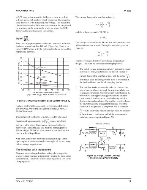
Zero-crossing optocouplers can be used to switch inductive<br />
loads at currents less than 100 mA (Figure 24). However a<br />
power TRIAC along with the optocoupler should be used <strong>for</strong><br />
higher load currents.<br />
LOAD CURRENT (mA RMS)<br />
80<br />
70<br />
60<br />
50<br />
40<br />
30<br />
20<br />
10<br />
C S = 0.01<br />
C S = 0.001<br />
NO SNUBBER<br />
0<br />
20 30 40 50 60 70 80 90 100<br />
T A, AMBIENT TEMPERATURE (°C)<br />
(R S = 100Ω, V RMS = 220V, POWER FACTOR = 0.5)<br />
Figure 24. MOC3062 Inductive Load Current versus T A<br />
A phase controllable optocoupler is recommended with a<br />
power device. When the load current is small, a MAC97<br />
TRIAC is suitable.<br />
Unusual circuit conditions sometimes lead to unwanted<br />
operation of an optocoupler in ⎛dV<br />
------ ⎞<br />
⎝<br />
mode. Very large<br />
dt ⎠c<br />
currents in the power device cause increased voltages<br />
between MT2 <strong>and</strong> the gate that hold the optocoupler on.<br />
Use of a larger TRIAC or other measures that limit inrush<br />
current solve this problem.<br />
Very short conduction times leave residual charge in the<br />
optocoupler. A minimum conduction angle allows recovery<br />
be<strong>for</strong>e voltage reapplication.<br />
The <strong>Snubber</strong> with Inductance<br />
Consider an overdamped snubber using a large capacitor<br />
whose voltage changes insignificantly during the time under<br />
consideration. The circuit reduces to an equivalent L/R series<br />
charging circuit.<br />
e = i R S<br />
The voltage wave across the TRIAC has an exponential rise<br />
with maximum rate at t = 0. Taking its derivative gives its<br />
value as:<br />
⎛------<br />
⎞<br />
⎝ dt ⎠0<br />
VR<br />
= ---------- S<br />
L<br />
Highly overdamped snubber circuits are not practical<br />
designs. The example illustrates several properties:<br />
1. The initial voltage appears completely across the circuit<br />
inductance. Thus, it determines the rate of change of<br />
dV<br />
current through the snubber resistor <strong>and</strong> the initial ------ .<br />
dt<br />
This result does not change when there is resistance in<br />
the load <strong>and</strong> holds true <strong>for</strong> all damping factors.<br />
2. The snubber works because the inductor controls the<br />
rate of current change through the resistor <strong>and</strong> the rate<br />
of capacitor charging. <strong>Snubber</strong> design cannot ignore the<br />
inductance. This approach suggests that the snubber<br />
capacitance is not important but that is only true <strong>for</strong><br />
this hypothetical condition. The snubber resistor shunts<br />
the thyristor causing unacceptable leakage when the<br />
capacitor is not present. If the power loss is tolerable,<br />
dV<br />
------ can be controlled without the capacitor. An example<br />
dt<br />
is the soft-start circuit used to limit inrush current in<br />
switching power supplies (Figure 25).<br />
E<br />
E<br />
AC LINE SNUBBER<br />
L<br />
AC LINE SNUBBER<br />
L<br />
<strong>Snubber</strong> with no C<br />
RECTIFIER<br />
BRIDGE<br />
dV<br />
dt<br />
R S<br />
= ERS<br />
φ L<br />
R S<br />
Figure 25. Surge Current Limiting<br />
For a Switching <strong>Power</strong> Supply<br />
G<br />
G<br />
RECTIFIER<br />
BRIDGE<br />
C1<br />
C1<br />
REV. 4.01 6/24/02 11


