

AN-3008 RC Snubber Networks for Thyristor Power Control and ...
AN-3008 RC Snubber Networks for Thyristor Power Control and ...
AN-3008 RC Snubber Networks for Thyristor Power Control and ...

Create successful ePaper yourself
Turn your PDF publications into a flip-book with our unique Google optimized e-Paper software.
APPLICATION NOTE<br />
<strong>AN</strong>-<strong>3008</strong><br />
dV<br />
The noise induced into a circuit is proportional to ------ when<br />
dt<br />
dI<br />
coupling is by stray capacitance, <strong>and</strong> ---- when the coupling<br />
dt<br />
is by mutual inductance. Best suppression requires the use of<br />
a voltage limiting device along with a rate limiting CRL<br />
snubber. The thyristor is best protected by preventing turn-on<br />
dV<br />
from ------ or breakover. The circuit should be designed <strong>for</strong><br />
dt<br />
what can happen instead of what normally occurs.<br />
In Figure 30, a MOV connected across the line protects<br />
many parallel circuit branches <strong>and</strong> their loads. The MOV<br />
dI<br />
defines the maximum input voltage <strong>and</strong> ---- through the load.<br />
dt<br />
dV<br />
With the snubber it sets the maximum ------ <strong>and</strong> peak voltage<br />
dt<br />
across the thyristor. The MOV must be large because there is<br />
little surge limiting impedance to prevent its burn-out.<br />
V MAX<br />
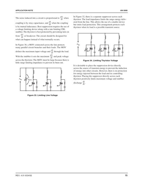
In Figure 32, there is a separate suppressor across each<br />
thyristor. The load impedance limits the surge energy delivered<br />
from the line. This allows the use of a smaller device<br />
but omits load protection. This arrangement protects each<br />
thyristor when its load is a possible transient source.<br />
Figure 34. Limiting <strong>Thyristor</strong> Voltage<br />
It is desirable to place the suppression device directly<br />
across the source of transient energy to prevent the induction<br />
of energy into other circuits. However, there is no protection<br />
<strong>for</strong> energy injected between the load <strong>and</strong> its controlling<br />
thyristor. Placing the suppressor directly across each<br />
thyristor positively limits maximum voltage <strong>and</strong> snubber<br />
dI<br />
discharge ---- .<br />
dt<br />
Figure 33. Limiting Line Voltage<br />
REV. 4.01 6/24/02 15


