

AN-3008 RC Snubber Networks for Thyristor Power Control and ...
AN-3008 RC Snubber Networks for Thyristor Power Control and ...
AN-3008 RC Snubber Networks for Thyristor Power Control and ...

Create successful ePaper yourself
Turn your PDF publications into a flip-book with our unique Google optimized e-Paper software.
<strong>AN</strong>-<strong>3008</strong><br />
Transient <strong>and</strong> Noise Suppression<br />
Transients arise internally from normal circuit operation or<br />
externally from the environment. The latter is particularly<br />
frustrating because the transient characteristics are undefined.<br />
A statistical description applies. Greater or smaller<br />
stresses are possible. Long duration high voltage transients<br />
are much less probable than those of lower amplitude <strong>and</strong><br />
higher frequency. Environments with infrequent lightning<br />
<strong>and</strong> load switching see transient voltages below 3.0 kV.<br />
APPLICATION NOTE<br />
The natural frequencies <strong>and</strong> impedances of indoor ac wiring<br />
result in damped oscillatory surges with typical frequencies<br />
ranging from 30 kHz to 1.5 MHz. Surge amplitude depends<br />
on both the wiring <strong>and</strong> the source of surge energy. Disturbances<br />
tend to die out at locations far away from the source.<br />
Spark-over (6.0 kV in indoor ac wiring) sets the maximum<br />
voltage when transient suppressors are not present. Transients<br />
closer to service entrance or in heavy wiring have<br />
higher amplitudes, longer durations, <strong>and</strong> more damping<br />
because of the lower inductance at those locations.<br />
10K<br />
1000<br />
RS(OHMS)<br />
100<br />
0.6A RMS<br />
2.5A<br />
5A<br />
10A<br />
20A<br />
40A<br />
80A<br />
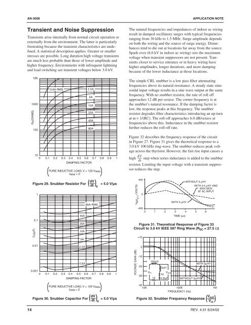
The simple CRL snubber is a low pass filter attenuating<br />
frequencies above its natural resonance. A steady state sinusoidal<br />
input voltage results in a sine wave output at the same<br />
frequency. With no snubber resistor, the rate of roll off<br />
approaches 12 dB per octave. The corner frequency is at<br />
the snubber’s natural resonance. If the damping factor is<br />
low, the response peaks at this frequency. The snubber<br />
resistor degrades filter characteristics introducing an up-turn<br />
at ω = 1/(<strong>RC</strong>). The roll-off approaches 6.0 dB/octave at<br />
frequencies above this. Inductance in the snubber resistor<br />
further reduces the roll-off rate.<br />
WITH 5µHY<br />
Figure 32 describes the frequency response of the circuit<br />
in Figure 27. Figure 31 gives the theoretical response to a<br />
3.0 kV 100 kHz ring-wave. The snubber reduces peak voltage<br />
across the thyristor. However, the fast rise input causes a<br />
10<br />
dV<br />
0 0.1 0.2 0.3 0.4 0.5 0.6 0.7 0.8 0.9 1 high ------ step when series inductance is added to the snubber<br />
dt<br />
DAMPING FACTOR<br />
resistor. Limiting the input voltage with a transient suppressor<br />
dV<br />
Figure 30. <strong>Snubber</strong> Capacitor For (<br />
dt<br />
) = 5.0 V/µs<br />
Figure 32. <strong>Snubber</strong> Frequency Response<br />
c<br />
PURE INDUCTIVE LOAD, V = 120 V RMS,<br />
reduces the step.<br />
I RRM = 0<br />
400<br />
dV<br />
WITHOUT 5 µHY<br />
Figure 29. <strong>Snubber</strong> Resistor For (<br />
dt<br />
) = 5.0 V/µs<br />
c<br />
WITH 5 5 µHY <strong>AN</strong>D<br />
450V MOV<br />
AT AC INPUT<br />
1<br />
0<br />
WITH 5 µHY<br />
80A RMS<br />
-400<br />
0 1 2 3 4 5 6<br />
40A<br />
TIME (µs)<br />
0.1<br />
20A<br />
Figure 31. Theoretical Response of Figure 33<br />
Circuit to 3.0 kV IEEE 587 Ring Wave (R SC = 27.5 Ω)<br />
10A<br />
5A<br />
+10<br />
0.01<br />
2.5A<br />
0<br />
-10<br />
0.6A<br />
100µH<br />
0.001<br />
V<br />
0 0.1 0.2 0.3 0.4 0.5 0.6 0.7 0.8 0.9 1<br />
in V out<br />
-30<br />
10<br />
DAMPING FACTOR<br />
12 0.33µF WITHOUT 5µHY<br />
-20<br />
5µH<br />
-40<br />
PURE INDUCTIVE LOAD, V = 120 V RMS,<br />
10K<br />
100K<br />
I RRM = 0<br />
FREQUENCY (Hz)<br />
1M<br />
CS(µF)<br />
14 REV. 4.01 6/24/02<br />
V MT2-1 (VOLTS)<br />
VOLTAGE GAIN (dB)<br />
V<br />
(<br />
out<br />
V in<br />
)


