

AN-3008 RC Snubber Networks for Thyristor Power Control and ...
AN-3008 RC Snubber Networks for Thyristor Power Control and ...
AN-3008 RC Snubber Networks for Thyristor Power Control and ...

You also want an ePaper? Increase the reach of your titles
YUMPU automatically turns print PDFs into web optimized ePapers that Google loves.
APPLICATION NOTE<br />
<strong>AN</strong>-<strong>3008</strong><br />
Conditions Influencing<br />
dV<br />
Commutating ------ depends on charge storage <strong>and</strong> recovery<br />
dt<br />
dV<br />
dynamics in addition to the variables influencing static ------ .<br />
dt<br />
High temperatures increase minority carrier life-time <strong>and</strong> the<br />
size of recovery currents, making turn-off more difficult.<br />
Loads that slow the rate of current zero-crossing aid turn-off.<br />
Those with harmonic content hinder turn-off.<br />
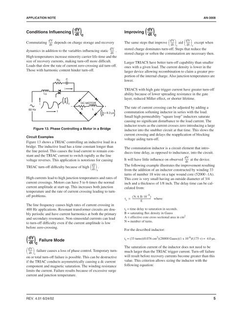
Figure 13. Phase <strong>Control</strong>ling a Motor in a Bridge<br />
Circuit Examples<br />
Figure 13 shows a TRIAC controlling an inductive load in a<br />
bridge. The inductive load has a time constant longer than<br />
the line period. This causes the load current to remain constant<br />
<strong>and</strong> the TRIAC current to switch rapidly as the line<br />
voltage reverses. This application is notorious <strong>for</strong> causing<br />
TRIAC turn-off difficulty because of high ⎛dI<br />
----⎞<br />
⎝<br />
.<br />
dt⎠<br />
High currents lead to high junction temperatures <strong>and</strong> rates of<br />
current crossings. Motors can have 5 to 6 times the normal<br />
current amplitude at start-up. This increases both junction<br />
temperature <strong>and</strong> the rate of current crossing leading to turnoff<br />
problems.<br />
The line frequency causes high rates of current crossing in<br />
400 Hz applications. Resonant trans<strong>for</strong>mer circuits are doubly<br />
periodic <strong>and</strong> have current harmonics at both the primary<br />
<strong>and</strong> secondary resonance. Non-sinusoidal currents can lead<br />
to turn-off difficulty even if the current amplitude is low<br />
be<strong>for</strong>e zero-crossing.<br />
Failure Mode<br />
i<br />
C<br />
dV<br />
( )<br />
dt c<br />
R S<br />
L S<br />
dl<br />
dt<br />
i<br />
c DC MOTOR<br />
– +<br />
60 Hz R L<br />
t<br />
L<br />
> 8.3 µs<br />
R<br />
dV<br />
( )<br />
dt c<br />
⎛dV<br />
------ ⎞<br />
⎝<br />
failure causes a loss of phase control. Temporary turnon<br />
or total turn-off failure is possible. This can be destructive<br />
dt ⎠c<br />
if the TRIAC conducts asymmetrically causing a dc current<br />
component <strong>and</strong> magnetic saturation. The winding resistance<br />
limits the current. Failure results because of excessive surge<br />
current <strong>and</strong> junction temperature.<br />
c<br />
dV<br />
Improving ( )<br />
dt c<br />
The same steps that improve ⎛dV<br />
------ ⎞ aid ⎛dV<br />
------ ⎞<br />
⎝<br />
except when<br />
dt ⎠s<br />
⎝ dt ⎠c<br />
stored charge dominates turn-off. Steps that reduce the<br />
stored charge or soften the commutation are necessary then.<br />
Larger TRIACS have better turn-off capability than smaller<br />
ones with a given load. The current density is lower in the<br />
larger device allowing recombination to claim a greater proportion<br />
of the internal charge. Also junction temperatures are<br />
lower.<br />
TRIACS with high gate trigger current have greater turn-off<br />
ability because of lower spreading resistance in the gate<br />
layer, reduced Miller effect, or shorter lifetime.<br />
The rate of current crossing can be adjusted by adding a<br />
commutation softening inductor in series with the load.<br />
Small high permeability “square loop” inductors saturate<br />
causing no significant disturbance to the load current. The<br />
inductor resets as the current crosses zero introducing a large<br />
inductor into the snubber circuit at that time. This slows the<br />
current crossing <strong>and</strong> delays the reapplication of blocking<br />
voltage aiding turn-off.<br />
The commutation inductor is a circuit element that introduces<br />
time delay, as opposed to inductance, into the circuit.<br />
dV<br />
It will have little influence on observed ------ at the device.<br />
dt<br />
The following example illustrates the improvement resulting<br />
from the addition of an inductor constructed by winding 33<br />
turns of number 18 wire on a tape wound core (52000 -1A).<br />
This core is very small having an outside diameter of 3/4<br />
inch <strong>and</strong> a thickness of 1/8 inch. The delay time can be calculated<br />
from:<br />
( N A B 10 – 8 )<br />
t s = -------------------------------- where:<br />
E<br />
t s = time delay to saturation in seconds.<br />
B = saturating flux density in Gauss<br />
A = effective core cross sectional area in cm 2<br />
N = number of turns.<br />
For the described inductor:<br />
t s = (33 turns)(0.076 cm 2 )(28000 Gauss)(1 x 10 -8 )/(175 v) = 4.0 µs.<br />
The saturation current of the inductor does not need to be<br />
much larger than the TRIAC trigger current. Turn-off failure<br />
will result be<strong>for</strong>e recovery currents become greater than this<br />
value. This criterion allows sizing the inductor with the<br />
following equation:<br />
REV. 4.01 6/24/02 5


