

AN-3008 RC Snubber Networks for Thyristor Power Control and ...
AN-3008 RC Snubber Networks for Thyristor Power Control and ...
AN-3008 RC Snubber Networks for Thyristor Power Control and ...

Create successful ePaper yourself
Turn your PDF publications into a flip-book with our unique Google optimized e-Paper software.
APPLICATION NOTE<br />
<strong>AN</strong>-<strong>3008</strong><br />
L<br />
C<br />
R<br />
Core remanence <strong>and</strong> saturation cause surge currents. They<br />
depend on trigger angle, line impedance, core characteristics,<br />
<strong>and</strong> direction of the residual magnetization. For example,<br />
a 2.8 kVA 120 V 1:1 trans<strong>for</strong>mer with a 1.0 ampere load<br />
produced 160 ampere currents at start-up. Soft starting the<br />
circuit at a small conduction angle reduces this current.<br />
L DEPENDS ON CURRENT AMPLITUDE, CORE<br />
SATURATION<br />
R INCLUDES CORE LOSS, WINDING R. INCREASES<br />
WITH FREQUENCY<br />
C WINDING CAPACIT<strong>AN</strong>CE. DEPENDS ON<br />
INSULATION, WIRE SIZE, GEOMETRY<br />
Complex Loads<br />
Figure 19. Inductor Model<br />
Many real-world inductances are non-linear. Their core<br />
materials are not gapped causing inductance to vary with<br />
current amplitude. Small signal measurements poorly<br />
characterize them. For modeling purposes, it is best to<br />
measure them in the actual application.<br />
Complex load circuits should be checked <strong>for</strong> transient voltages<br />
<strong>and</strong> currents at turn-on <strong>and</strong> turn-off. With a capacitive<br />
load, turn-on at peak input voltage causes the maximum<br />
surge current. Motor starting current runs 4 to 6 times the<br />
steady state value. Generator action can boost voltages above<br />
the line value. Inc<strong>and</strong>escent lamps have cold start currents 10<br />
to 20 times the steady state value. Trans<strong>for</strong>mers generate<br />
voltage spikes when they are energized. <strong>Power</strong> factor correction<br />
circuits <strong>and</strong> switching devices create complex loads. In most<br />
cases, the simple CRL model allows an approximate snubber<br />
design. However, there is no substitute <strong>for</strong> testing <strong>and</strong> measuring<br />
the worst case load conditions.<br />
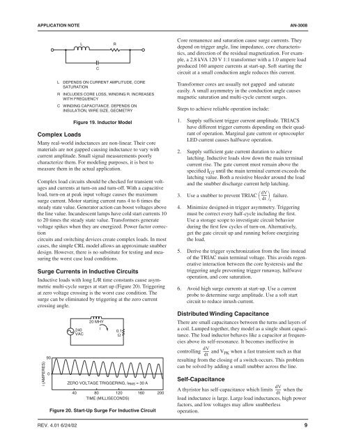
Surge Currents in Inductive Circuits<br />
Inductive loads with long L/R time constants cause asymmetric<br />
multi-cycle surges at start up (Figure 20). Triggering<br />
at zero voltage crossing is the worst case condition. The<br />
surge can be eliminated by triggering at the zero current<br />
crossing angle.<br />
i (AMPERES)<br />
90<br />
0<br />
240<br />
VAC<br />
40<br />
20 MHY<br />
i<br />
0.1<br />
Ω<br />
ZERO VOLTAGE TRIGGERING, I RMS = 30 A<br />
80 120 160 200<br />
TIME (MILLISECONDS)<br />
Figure 20. Start-Up Surge For Inductive Circuit<br />
Trans<strong>for</strong>mer cores are usually not gapped <strong>and</strong> saturate<br />
easily. A small asymmetry in the conduction angle causes<br />
magnetic saturation <strong>and</strong> multi-cycle current surges.<br />
Steps to achieve reliable operation include:<br />
1. Supply sufficient trigger current amplitude. TRIACS<br />
have different trigger currents depending on their quadrant<br />
of operation. Marginal gate current or optocoupler<br />
LED current causes halfwave operation.<br />
2. Supply sufficient gate current duration to achieve<br />
latching. Inductive loads slow down the main terminal<br />
current rise. The gate current must remain above the<br />
specified I GT until the main terminal current exceeds the<br />
latching value. Both a resistive bleeder around the load<br />
<strong>and</strong> the snubber discharge current help latching.<br />
3. Use a snubber to prevent TRIAC ⎛dV<br />
------ ⎞<br />
⎝<br />
failure.<br />
dt ⎠c<br />
4. Minimize designed-in trigger asymmetry. Triggering<br />
must be correct every half-cycle including the first.<br />
Use a storage scope to investigate circuit behavior<br />
during the first few cycles of turn-on. Alternatively,<br />
get the gate circuit up <strong>and</strong> running be<strong>for</strong>e energizing<br />
the load.<br />
5. Derive the trigger synchronization from the line instead<br />
of the TRIAC main terminal voltage. This avoids regenerative<br />
interaction between the core hysteresis <strong>and</strong> the<br />
triggering angle preventing trigger runaway, halfwave<br />
operation, <strong>and</strong> core saturation.<br />
6. Avoid high surge currents at start-up. Use a current<br />
probe to determine surge amplitude. Use a soft start<br />
circuit to reduce inrush current.<br />
Distributed Winding Capacitance<br />
There are small capacitances between the turns <strong>and</strong> layers of<br />
a coil. Lumped together, they model as a single shunt capacitance.<br />
The load inductor behaves like a capacitor at frequencies<br />
above its self-resonance. It becomes ineffective in<br />
dV<br />
controlling ------ <strong>and</strong> V PK when a fast transient such as that<br />
dt<br />
resulting from the closing of a switch occurs. This problem<br />
can be solved by adding a small snubber across the line.<br />
Self-Capacitance<br />
dV<br />
A thyristor has self-capacitance which limits ------ when the<br />
dt<br />
load inductance is large. Large load inductances, high power<br />
factors, <strong>and</strong> low voltages may allow snubberless<br />
operation.<br />
REV. 4.01 6/24/02 9


