PCIE-G41A2 PICMG 1.3 CPU card - iEi
PCIE-G41A2 PICMG 1.3 CPU card - iEi
PCIE-G41A2 PICMG 1.3 CPU card - iEi

Create successful ePaper yourself
Turn your PDF publications into a flip-book with our unique Google optimized e-Paper software.
<strong>PCIE</strong>-<strong>G41A2</strong> <strong>PICMG</strong> <strong>1.3</strong> <strong>CPU</strong> <strong>card</strong><br />
Description Label Type<br />
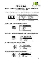
Clear CMOS jumper J_CMOS1 3-pin header<br />
Table 4-1: Jumpers<br />
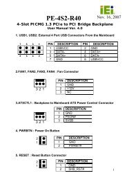
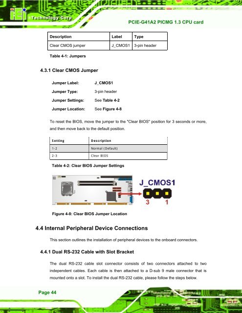
4.3.1 Clear CMOS Jumper<br />
Jumper Label:<br />
Jumper Type:<br />
J_CMOS1<br />
3-pin header<br />
Jumper Settings: See Table 4-2<br />
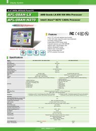
Jumper Location: See Figure 4-8<br />
To reset the BIOS, move the jumper to the "Clear BIOS" position for 3 seconds or more,<br />
and then move back to the default position.<br />
Setting<br />
Description<br />
1-2 Normal (Default)<br />
2-3 Clear BIOS<br />
Table 4-2: Clear BIOS Jumper Settings<br />
Figure 4-8: Clear BIOS Jumper Location<br />
4.4 Internal Peripheral Device Connections<br />
This section outlines the installation of peripheral devices to the onboard connectors.<br />
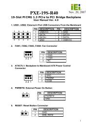
4.4.1 Dual RS-232 Cable with Slot Bracket<br />
The dual RS-232 cable slot connector consists of two connectors attached to two<br />
independent cables. Each cable is then attached to a D-sub 9 male connector that is<br />
mounted onto a slot. To install the dual RS-232 cable, please follow the steps below.<br />
Page 44