azu_td_1349475_sip1_... - Arizona Campus Repository
azu_td_1349475_sip1_... - Arizona Campus Repository
azu_td_1349475_sip1_... - Arizona Campus Repository
You also want an ePaper? Increase the reach of your titles
YUMPU automatically turns print PDFs into web optimized ePapers that Google loves.
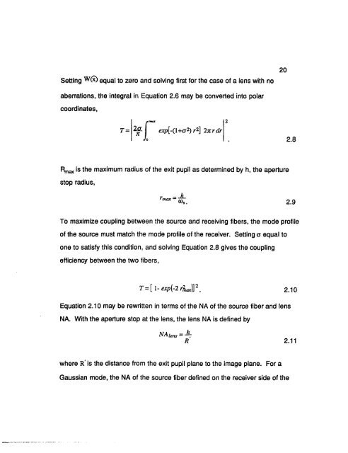
Setting w (x) equal to zero and solving first for the case of a lens with no<br />
20<br />
aberrations, the integral in Equation 2.6 may be converted into polar<br />
coordinates,<br />
|<br />
«muz 2<br />
I exp[-{\+o 2 ) r 2 ] 2itrdr<br />
Jo 2.8<br />
Rmax is the maximum radius of the exit pupil as determined by h, the aperture<br />
stop radius,<br />
r = -hmax<br />
®S. 2.9<br />
To maximize coupling between the source and receiving fibers, the mode profile<br />
of the source must match the mode profile of the receiver. Setting a equal to<br />
one to satisfy this condition, and solving Equation 2.8 gives the coupling<br />
efficiency between the two fibers,<br />
T = [l-exp{-2r% iax)] 2 m 2.10<br />
Equation 2.10 may be rewritten in terms of the NA of the source fiber and lens<br />
NA. With the aperture stop at the lens, the lens NA is defined by<br />
NA lens = -<br />
h 7<br />
R 2.11<br />
where R' is the distance from the exit pupil plane to the image plane. For a<br />
Gaussian mode, the NA of the source fiber defined on the receiver side of the


