azu_td_1349475_sip1_... - Arizona Campus Repository
azu_td_1349475_sip1_... - Arizona Campus Repository
azu_td_1349475_sip1_... - Arizona Campus Repository

Create successful ePaper yourself
Turn your PDF publications into a flip-book with our unique Google optimized e-Paper software.
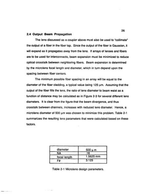
2.4 Output Beam Propagation<br />
26<br />
The lens discussed as a coupler above must also be used to "collimate"<br />
the output of a fiber in the fiber tap. Since the output of the fiber is Gaussian, it<br />
will expand as it propagates away from the lens. If arrays of lenses and fibers<br />
are to be used for interconnects, beam expansion must be minimized to reduce<br />
optical crosstalk between neighboring fibers. Beam expansion is determined<br />
by the microlens focal length ana diameter, which in turn depend upon the<br />
spacing between fiber centers.<br />
The minimum possible fiber spacing in an array will be equal to the<br />
diameter of the fiber cladding, a typical value being 125 nm. Assuming that the<br />
output of the fiber fills the lens, the ratio of lens diameter to beam waist as a<br />
function of distance may be calculated as in Figure 2-3 for several different lens<br />
diameters. It is clear from the figure that the beam divergence, and thus<br />
crosstalk between channels, increases with reduced lens diameter. Hence, a<br />
microlens diameter of 500 |am was chosen to minimize this problem. Table 2-1<br />
summarizes the resulting lens parameters that were calculated based on these<br />
factors.<br />
diameter<br />
500 p.m<br />
NA .16<br />
focal length 1.5625 mm<br />
F# 3.125<br />
Table 2-1 Microlens design parameters.