MV design guide - Schneider Electric
MV design guide - Schneider Electric
MV design guide - Schneider Electric

Create successful ePaper yourself
Turn your PDF publications into a flip-book with our unique Google optimized e-Paper software.
Design rules<br />
Busbar calculation<br />
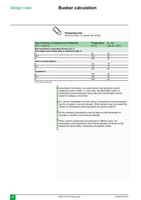
Temperature rise<br />
Taken from table V of standard IEC 60 694<br />
Type of device, of material and of dielectric Temperature (θ - θn)<br />
(Cf: 1, 2 and 3) θ (°C) with θn = 40°C<br />
Bolt connected or equivalent devices (Cf: 7)<br />
bare copper, bare copper alloy or aluminium alloy in<br />
air 90 50<br />
SF6 * 105 65<br />
oil 100 60<br />
silver or nickel plated in<br />
air 115 75<br />
SF6 115 75<br />
oil 100 60<br />
tin-plated in<br />
air 105 65<br />
SF6 105 65<br />
oil 100 60<br />
* SF6 (sulphur hexafluoride)<br />
1<br />
2<br />
3<br />
7<br />
According to its function, the same device may belong to several<br />
categories given in table V. In this case, the admissible values of<br />
temperature and temperature rise to take into consideration are the<br />
lowest for category concerned.<br />
For vacuum switchgear, the limit values of temperature and temperature<br />
rise do not apply to vacuum devices. Other devices must not exceed the<br />
values for temperature and temperature rise given in table V.<br />
All the necessary precautions must be taken so that absolutely no<br />
damage is caused to surrounding materials.<br />
When contact components are protected in different ways, the<br />
temperature and temperature rises that are allowed are those for the<br />
element for which table V authorises the highest values.<br />
22 Merlin Gerin <strong>MV</strong> <strong>design</strong> <strong>guide</strong> <strong>Schneider</strong> <strong>Electric</strong>