MV design guide - Schneider Electric
MV design guide - Schneider Electric
MV design guide - Schneider Electric

Create successful ePaper yourself
Turn your PDF publications into a flip-book with our unique Google optimized e-Paper software.
Switchgear<br />
definition<br />
Medium voltage circuit breaker<br />
Rated capacitor bank inrush making current<br />
(cf. § 4.111 IEC 60 056)<br />
The rated closing current for capacitor banks is the peak current value<br />
that the circuit breaker must be capable of making at the rated voltage.<br />
The value of the circuit breaker's rated closing current must be greater<br />
than the making current for the capacitor bank. In service, the frequency<br />
of the pick-up current is normally in the region of 2 - 5 kHz.<br />
Rated small inductive breaking current<br />
(cf. § 4.112 IEC 60 056)<br />
The breaking of a low inductive current (several amperes to several tens<br />
of amperes) causes overvoltages. The type of circuit breaker will be<br />
chosen so that the overvoltages that appear do not damage the insulation<br />
of the current consumers (transformer, motors).<br />
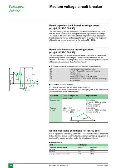
U<br />
Um<br />
Uf<br />
Uc<br />
Ud<br />
Uif<br />
Up<br />
t<br />
c The figure opposite shows the various voltages on the load side<br />
Uf : instantaneous network voltage value<br />
Uc : network voltage at the moment of breaking<br />
Um : extinction point<br />
Uif : overvoltage relative to earth<br />
Up : maximum overvoltage relative to earth<br />
Ud : maximum peak-to-peak amplitude of the overvoltage<br />
due to restrike.<br />
c Insulation level of motors<br />
IEC 60 034 stipulates the insulation level of motors.<br />
Power frequency and impulse withstand testing is given in the table below<br />
(rated insulation levels for rotary sets).<br />
Insulation Test at 50 (60) Hz Impulse test<br />
rms. value<br />
Between turns<br />
(4 Ur + 5) kV<br />
4.9 pu + 5 = 31 kV at 6.6 kV<br />
(50% on the sample)<br />
increase time 0.5 µs<br />
Relative (2 Ur + 5) kV (4 Ur + 5) kV<br />
to earth 2Ur + 1 ⇒ 2(2Ur + 1) ⇒ 0 4.9 pu + 5 = 31 kV at 6.6 kV<br />
14 kV ⇒ 28 kV ⇒ 0 increase time 1.2 µs<br />
1 kV/s<br />
t<br />
0<br />
1 mn<br />
Normal operating conditions (cf. IEC 60 694)<br />
For all equipment functioning under other conditions than those described<br />
below, derating should be carried out (see derating chapter). Equipment is<br />
<strong>design</strong>ed for normal operation under the following conditions:<br />
c Temperature<br />
0°C Installation<br />
Instantaneous ambient Indoor Outdoor<br />
minimal -5°C -25°C<br />
maximal +40°C +40°C<br />
average daily maximum value 35°C 35°C<br />
52 Merlin Gerin <strong>MV</strong> <strong>design</strong> <strong>guide</strong> <strong>Schneider</strong> <strong>Electric</strong>