

Users Manual WP 900 UHF.pdf - Jotron
Users Manual WP 900 UHF.pdf - Jotron
Users Manual WP 900 UHF.pdf - Jotron

You also want an ePaper? Increase the reach of your titles
YUMPU automatically turns print PDFs into web optimized ePapers that Google loves.
Installation Guide<br />
T942C- and T942C/2 Central Unit<br />
TD 91684GB<br />
Handook page<br />
15/128<br />
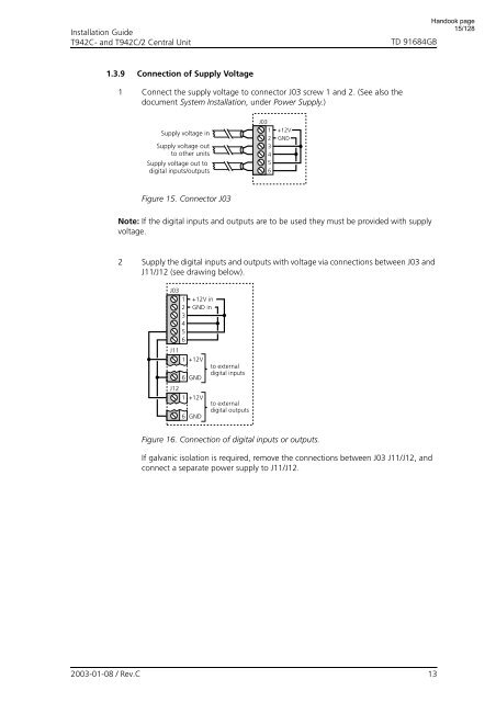
1.3.9 Connection of Supply Voltage<br />
1 Connect the supply voltage to connector J03 screw 1 and 2. (See also the<br />
document System Installation, under Power Supply.)<br />
Supply voltage in<br />
Supply voltage out<br />
to other units<br />
Supply voltage out to<br />
digital inputs/outputs<br />
J03<br />
1 +12V<br />
2 GND<br />
3<br />
4<br />
5<br />
6<br />
Figure 15. Connector J03<br />
Note: If the digital inputs and outputs are to be used they must be provided with supply<br />
voltage.<br />
2 Supply the digital inputs and outputs with voltage via connections between J03 and<br />
J11/J12 (see drawing below).<br />
J03<br />
1 +12V in<br />
2 GND in<br />
3<br />
4<br />
5<br />
6<br />
J11<br />
1 +12V<br />
to external<br />
digital inputs<br />
6 GND<br />
J12<br />
1 +12V<br />
to external<br />
6 GND<br />
digital outputs<br />
Figure 16. Connection of digital inputs or outputs.<br />
If galvanic isolation is required, remove the connections between J03 J11/J12, and<br />
connect a separate power supply to J11/J12.<br />
2003-01-08 / Rev.C<br />
13


