

Users Manual WP 900 UHF.pdf - Jotron
Users Manual WP 900 UHF.pdf - Jotron
Users Manual WP 900 UHF.pdf - Jotron

You also want an ePaper? Increase the reach of your titles
YUMPU automatically turns print PDFs into web optimized ePapers that Google loves.
Handook page<br />
36/128<br />
Installation Guide<br />
H/U952T Terminal Transmitter<br />
TD 92022GB<br />
3.6 Connection of Supply Voltage<br />
• Connect supply voltage to connector J102 screw 1 and 2. See also the System<br />
Installation document, under Power Supply.<br />
H/U952T<br />
Supply voltage-in<br />
Supply voltage-out<br />
J102<br />
1 +12V<br />
2 GND<br />
3 +12V<br />
4 GND<br />
Figure 10. Power supply connector.<br />
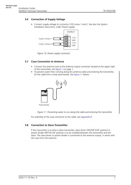
3.7 Coax Connection to Antenna<br />
• Connect the antenna coax to the antenna output connector located at the upper right<br />
of the transmitter, see figure 1 on page 1.<br />
• To prevent water from running along the antenna cable and entering the transmitter,<br />
let the cable form a loop downwards. See figure 11 below.<br />
Transmitter<br />
Figure 11. Preventing water to run along the cable and entering the transmitter.<br />
For assembly of the coax connector to the cable, see Appendix B.<br />
3.8 Connection to Slave Transmitter<br />
If the transmitter is to drive a slave transmitter, slave driver U952DR (<strong>UHF</strong> systems) or<br />
power divider MPT-50 (HF systems) is to be installed between the transmitter and the<br />
slave. The slave driver or power divider is connected to the antenna output, in series with<br />
the coax from the antenna.<br />
2002-11-13/ Rev. A<br />
7


