

Users Manual WP 900 UHF.pdf - Jotron
Users Manual WP 900 UHF.pdf - Jotron
Users Manual WP 900 UHF.pdf - Jotron

Create successful ePaper yourself
Turn your PDF publications into a flip-book with our unique Google optimized e-Paper software.
Installation Guide<br />
PBX Interface T942PX<br />
TD 91012GB<br />
Handook page<br />
53/128<br />
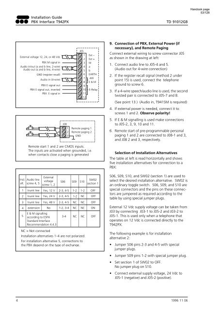
External voltage 12, 24, or 48 Vdc<br />
PBX M signal in<br />
Audio in/out (a and b line, 2-wire)<br />
Audio out (a and b line, 4-wire)<br />
GND (register recall)<br />
Audio in (4-wire)<br />
PBX E signal out<br />
PBX E signal out, inverted<br />
PBX E signal in<br />
J05<br />
1 Ext –<br />
2 Ext +<br />
3 M<br />
4 a<br />
5 b<br />
6 EARTH<br />
7 4W<br />
8 E & M<br />
9<br />
10 E-Relay<br />
11<br />
12<br />
J08<br />
1 Remote paging 1<br />
2 Remote paging 2<br />
3 GND<br />
9. Connection of PBX, External Power (if<br />
necessary), and Remote Paging<br />
Connect external wiring to screw connector J05<br />
as shown in the drawing at left:<br />
1. Connect audio line to J05-4 and 5.<br />
(Audio out for 4-wire connection)<br />
2. If the register recall signal (method 2 under<br />
point 15) is used, connect the telephone<br />
ground to screw 6.<br />
3. If a 4-wire speech/audio line is used, the second<br />
twisted pair is connected to J05-7 and 8.<br />
(See point 13.) (Audio in, T941SM is required)<br />
4. If external power is needed, connect it to<br />
screws 1 and 2. Observe polarity!<br />
5. If E & M signalling is used make connections<br />
to J05-2, 3, 9, 10 and 11.<br />
6. Remote start of pre-programmable personal<br />
paging 1 and 2 are connected to J08-1 and 3,<br />
and J08 2 and 3, respectively.<br />
Inst.<br />
alt.<br />
1<br />
2<br />
Remote start 1 and 2 are CMOS inputs.<br />
The inputs are activated when grounded, i.e.<br />
when contacts close a paging is generated<br />
Audio line<br />
screw 4, 5<br />
trunk line<br />
trunk line<br />
External<br />
voltage<br />
screw 1, 2<br />
Yes, 12 V<br />
Yes, 24 V<br />
S06<br />
2-3, 4-5<br />
2-3, 4-5<br />
S09<br />
S10<br />
1-2 1-2<br />
1-2 NC<br />
SW02<br />
section 1<br />
OFF<br />
OFF<br />
3 trunk line Yes, 48 V 2-3, 4-5 NC NC OFF<br />
4 extension No 1-2, 3-4 NC NC ON<br />
E & M signalling<br />
5 according to ESPA 3-4 NC NC OFF<br />
Standard Interface<br />
Recommendation 4.4.3<br />
NC = Not connected<br />
Installation alternatives 1–4 are not polarized.<br />
For installation alternative 5, connections to<br />
the PBX depend on the type of exchange.<br />
Selection of Installation Alternatives<br />
The table at left is read horizontally and shows<br />
five installation alternatives for connection to a<br />
PBX:<br />
S06, S09, S10, and SW02 (section 1) are used to<br />
select the desired installation alternative. SW02 is<br />
an ordinary toggle switch. S06, S09, and S10 are<br />
special connectors and the pins on these connectors<br />
are jumpered as required according to the<br />
table by using special jumper plugs.<br />
External 12 Vdc supply voltage can be taken from<br />
J03 by connecting J03-1 to J05-2 and J03-2 to<br />
J05-1. This is used only when a telephone that<br />
operates on 12 Vdc is connected directly to the<br />
T942PX.<br />
The following example is for installation<br />
alternative 2:<br />
• Jumper S06 pins 2-3 and 4-5 with special<br />
jumper plugs.<br />
• Jumper S09 pins 1-2 with special jumper plug.<br />
• Set section 1 of SW02 to OFF.<br />
No jumper plug on S10.<br />
• Connect external supply voltage, 24 Vdc to<br />
J05-1 (negative) and J05-2 (positive).<br />
4 1996 11 06


