

Users Manual WP 900 UHF.pdf - Jotron
Users Manual WP 900 UHF.pdf - Jotron
Users Manual WP 900 UHF.pdf - Jotron

You also want an ePaper? Increase the reach of your titles
YUMPU automatically turns print PDFs into web optimized ePapers that Google loves.
Handook page<br />
32/128<br />
Installation Guide<br />
H/U952T Terminal Transmitter<br />
TD 92022GB<br />
LEDs<br />
LED100<br />
LED201<br />
LED300<br />
LED301<br />
LED302<br />
Flash PROM<br />
IC101<br />
Adjustable<br />
Components<br />
P400<br />
L301<br />
C444<br />
L401<br />
Function indicator for green, red, or orange indication.<br />
LED, TX ON, indicates carrier.<br />
LED, TX DATA ON, indicates paging.<br />
Indicates DSP running (blinks).<br />
Indicates speech on.<br />
Program memory<br />
Potentiometer, for calibration of output power.<br />
Inductance coil, for fine adjustment of reference frequency.<br />
Capacitor, for adjustment of VCO frequency. Note: Only U952T<br />
Inductance coil, for adjustment of VCO frequency. Note: Only H952T.<br />
3 Installation<br />
The unit should be placed in a dry environment. A temperature between 0 and +40°C is<br />
preferred. The transmitter will operate in the temp range -15 up to +55°C. The transmitter<br />
can be installed alone or together with other system units using the modular bus cabling<br />
or twisted-pair wiring.<br />
To prevent dust or moisture from damaging the electronics it is important to have the<br />
cover mounted after installation and during use.<br />
3.1 Mounting<br />
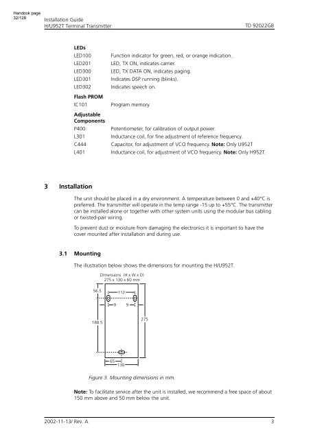
The illustration below shows the dimensions for mounting the H/U952T.<br />
Dimensions (H x W x D)<br />
275 x 130 x 60 mm<br />
56.5<br />
112<br />
9 9<br />
188.5<br />
275<br />
65<br />
130<br />
Figure 3. Mounting dimensions in mm.<br />
Note: To facilitate service after the unit is installed, we recommend a free space of about<br />
150 mm above and 50 mm below the unit.<br />
2002-11-13/ Rev. A<br />
3


