

Users Manual WP 900 UHF.pdf - Jotron
Users Manual WP 900 UHF.pdf - Jotron
Users Manual WP 900 UHF.pdf - Jotron

Create successful ePaper yourself
Turn your PDF publications into a flip-book with our unique Google optimized e-Paper software.
Installation Guide<br />
PBX Interface T942PX<br />
TD 91012GB<br />
Handook page<br />
55/128<br />
13. Selection of 2-Wire or 4-Wire<br />
Speech/Audio Line Connection<br />
Normally 2-wire speech/audio line connection is used.<br />
• 2-Wire Speech/Audio Line Connection:<br />
One twisted pair, connected to J05-4 and 5, is used<br />
for sending and receiving speech and DTMF tones.<br />
Set jumpers S12 and S13 to 1-2, and S14 to 2-3.<br />
S11 is not to be jumpered.<br />
• 4-Wire Speech/Audio Line Connection:<br />
One twisted pair, connected to J05-4 and 5, is used<br />
for sending speech and DTMF tones.<br />
A second twisted pair, connected to J05-7 and 8, is<br />
used for receiving speech and DTMF tones.<br />
Set jumpers S11 and S14 to 1-2.<br />
S12 and S13 are not to be jumpered.<br />
Note: Speech module T941SM is always<br />
required when the 4-wire speech/audio<br />
line connection is used.<br />
17. Installation Test Procedure<br />
1. Check that section 2 of switch SW02 is set to OFF.<br />
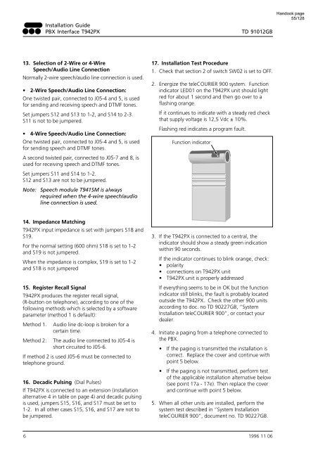
2. Energize the teleCOURIER <strong>900</strong> system. Function<br />
indicator LED01 on the T942PX unit should light<br />
red for about 1 second and then go over to a<br />
flashing orange.<br />
If it continues to indicate with a steady red check<br />
that supply voltage is 12,5 Vdc ± 10%.<br />
Flashing red indicates a program fault.<br />
Function indicator<br />
14. Impedance Matching<br />
T942PX input impedance is set with jumpers S18 and<br />
S19.<br />
For the normal setting (600 ohm) S18 is set to 1-2<br />
and S19 is not jumpered.<br />
When the impedance is complex, S19 is set to 1-2<br />
and S18 is not jumpered<br />
15. Register Recall Signal<br />
T942PX produces the register recall signal,<br />
(R-button on telephone), according to one of the<br />
following methods which is selected by a software<br />
parameter (method 1 is default):<br />
Method 1. Audio line dc-loop is broken for a<br />
certain time.<br />
Method 2: The audio line connected to J05-4 is<br />
short circuited to J05-6.<br />
If method 2 is used J05-6 must be connected to<br />
telephone ground.<br />
16. Decadic Pulsing (Dial Pulses)<br />
If T942PX is connected to an extension (installation<br />
alternative 4 in table on page 4) and decadic pulsing<br />
is used, jumpers S15, S16, and S17 must be set to<br />
1-2. In all other cases S15, S16, and S17 are not to<br />
be jumpered.<br />
3. If the T942PX is connected to a central, the<br />
indicator should show a steady green indication<br />
within 90 seconds.<br />
If the indicator continues to blink orange, check:<br />
• polarity<br />
• connections on T942PX unit<br />
• T942PX unit is properly addressed<br />
If everything seems to be in OK but the function<br />
indicator still blinks, the fault is probably located<br />
outside the T942PX. Check the other <strong>900</strong> units<br />
according to doc. no TD 90227GB, “System<br />
Installation teleCOURIER <strong>900</strong>”, or contact your<br />
dealer.<br />
4. Initiate a paging from a telephone connected to<br />
the PBX.<br />
• If the paging is transmitted the installation is<br />
correct. Replace the cover and continue with<br />
point 5 below.<br />
• If the paging is not transmitted, perform test<br />
of the applicable installation alternative below<br />
(see point 17a - 17e). Then replace the cover<br />
and continue with point 5 below.<br />
5. When all other units are installed, perform the<br />
system test described in “System Installation<br />
teleCOURIER <strong>900</strong>”, document no. TD 90227GB.<br />
6 1996 11 06


