

Users Manual WP 900 UHF.pdf - Jotron
Users Manual WP 900 UHF.pdf - Jotron
Users Manual WP 900 UHF.pdf - Jotron

You also want an ePaper? Increase the reach of your titles
YUMPU automatically turns print PDFs into web optimized ePapers that Google loves.
Handook page<br />
54/128<br />
Installation Guide<br />
PBX Interface T942PX<br />
TD 91012GB<br />
T942PX (J05)<br />
1<br />
2<br />
3<br />
4<br />
5<br />
6<br />
7<br />
8<br />
9<br />
10<br />
11<br />
12<br />
PBX<br />
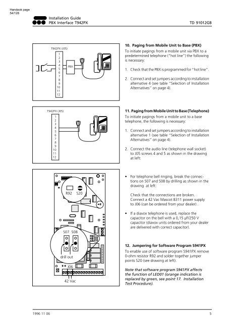
10. Paging from Mobile Unit to Base (PBX)<br />
To initiate pagings from a mobile unit via PBX to a<br />
predetermined telephone (“hot line”) the following<br />
is necessary:<br />
1. Check that the PBX is programmed for “hot line”.<br />
2. Connect and set jumpers according to installation<br />
alternative 4 (see table “Selection of Installation<br />
Alternatives” on page 4).<br />
T942PX (J05)<br />
1<br />
2<br />
3<br />
4<br />
5<br />
6<br />
7<br />
8<br />
9<br />
10<br />
11<br />
12<br />
11. Paging from Mobile Unit to Base (Telephone)<br />
To initiate pagings from a mobile unit to a base<br />
telephone, the following is necessary:<br />
1. Connect and set jumpers according to installation<br />
alternative 1 (see table “Selection of Installation<br />
Alternatives” on page 4).<br />
2. Connect the audio line (telephone wall socket)<br />
to J05 screws 4 and 5 as shown in the drawing<br />
at left:<br />
• For telephone bell ringing, break the connections<br />
on S07 and S08 by drilling as shown in the<br />
drawing at left:<br />
R92<br />
S20<br />
Check that the connections are broken.<br />
Connect a 42 Vac Mascot 8311 power supply<br />
to J06 (can be ordered from your dealer) .<br />
S07 S08<br />
• If a diavox telephone is used, replace the<br />
capacitor on the bell with a 0,15 µF/250 V<br />
capacitor (diavox units ordered from your dealer<br />
are delivered with correct capacitor).<br />
drill out<br />
J06<br />
42 Vac<br />
12. Jumpering for Software Program S941PX<br />
To enable use of software program S941PX remove<br />
0-ohm resistor R92 and solder together jumper<br />
points S20 (see drawing at left).<br />
Note that software program S941PX affects<br />
the function of LED01 (orange indication is<br />
replaced by green, see point 17. Installation<br />
Test Procedure).<br />
1996 11 06 5


