

Users Manual WP 900 UHF.pdf - Jotron
Users Manual WP 900 UHF.pdf - Jotron
Users Manual WP 900 UHF.pdf - Jotron

Create successful ePaper yourself
Turn your PDF publications into a flip-book with our unique Google optimized e-Paper software.
Handook page<br />
48/128<br />
Installation Guide<br />
Alarm Module T941AM8<br />
TD 90858GB<br />
11. System Error Indication (not used in CTS <strong>900</strong>)<br />
System fault relay RE01 has two parallel contacts<br />
that can be connected for make or break function.<br />
System fault 1<br />
System fault 2<br />
J04<br />
1 COM<br />
2 NO SYSTEM ERROR 1<br />
3 NC<br />
4 COM<br />
5 NO SYSTEM ERROR 2<br />
6 NC<br />
For system fault loop 1 connect the twisted-pair to<br />
J04: screw 1 and 2 for make contact<br />
screw 1 and 3 for break contact<br />
For system fault loop 2 connect the twisted-pair to<br />
J04: screw 4 and 5 for make contact<br />
screw 4 and 6 for break contact<br />
13. Installation Test Procedure<br />
1. Check that switch SW02 is set to OFF.<br />
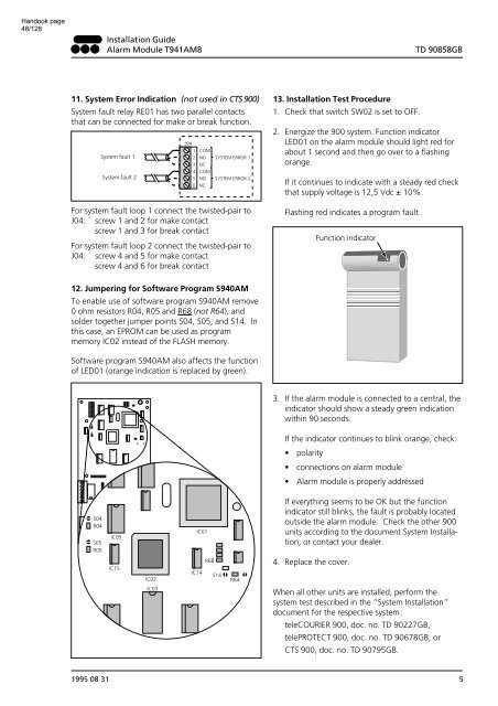
2. Energize the <strong>900</strong> system. Function indicator<br />
LED01 on the alarm module should light red for<br />
about 1 second and then go over to a flashing<br />
orange.<br />
If it continues to indicate with a steady red check<br />
that supply voltage is 12,5 Vdc ± 10%.<br />
Flashing red indicates a program fault.<br />
Function indicator<br />
12. Jumpering for Software Program S940AM<br />
To enable use of software program S940AM remove<br />
0 ohm resistors R04, R05 and R68 (not R64), and<br />
solder together jumper points S04, S05, and S14. In<br />
this case, an EPROM can be used as program<br />
memory IC02 instead of the FLASH memory.<br />
Software program S940AM also affects the function<br />
of LED01 (orange indication is replaced by green).<br />
3. If the alarm module is connected to a central, the<br />
indicator should show a steady green indication<br />
within 90 seconds.<br />
If the indicator continues to blink orange, check:<br />
• polarity<br />
• connections on alarm module<br />
• Alarm module is properly addressed<br />
S04<br />
R04<br />
S05<br />
R05<br />
IC05<br />
IC01<br />
If everything seems to be OK but the function<br />
indicator still blinks, the fault is probably located<br />
outside the alarm module: Check the other <strong>900</strong><br />
units according to the document System Installation,<br />
or contact your dealer.<br />
IC15<br />
IC02<br />
IC03<br />
R68<br />
IC14<br />
S14<br />
R64<br />
4. Replace the cover.<br />
When all other units are installed, perform the<br />
system test described in the “System Installation”<br />
document for the respective system:<br />
teleCOURIER <strong>900</strong>, doc. no. TD 90227GB,<br />
telePROTECT <strong>900</strong>, doc. no. TD 90678GB, or<br />
CTS <strong>900</strong>, doc. no. TD 90795GB.<br />
1995 08 31 5


