Tender Specification for Supply, Erection, Testing and ... - IDCO
Tender Specification for Supply, Erection, Testing and ... - IDCO
Tender Specification for Supply, Erection, Testing and ... - IDCO

You also want an ePaper? Increase the reach of your titles
YUMPU automatically turns print PDFs into web optimized ePapers that Google loves.
ISO 9001 & 14001 CORPORATION<br />
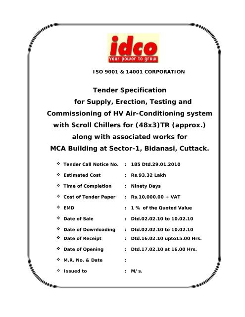
<strong>Tender</strong> <strong>Specification</strong><br />
<strong>for</strong> <strong>Supply</strong>, <strong>Erection</strong>, <strong>Testing</strong> <strong>and</strong><br />
Commissioning of HV Air-Conditioning system<br />
with Scroll Chillers <strong>for</strong> (48x3)TR (approx.)<br />
along with associated works <strong>for</strong><br />
MCA Building at Sector-1, Bidanasi, Cuttack.<br />
<strong>Tender</strong> Call Notice No.<br />
Estimated Cost<br />
Time of Completion<br />
Cost of <strong>Tender</strong> Paper<br />
EMD<br />
: 185 Dtd.29.01.2010<br />
: Rs.93.32 Lakh<br />
: Ninety Days<br />
: Rs.10,000.00 + VAT<br />
: 1 % of the Quoted Value<br />
Date of Sale : Dtd.02.02.10 to 10.02.10<br />
Date of Downloading : Dtd.02.02.10 to 10.02.10<br />
Date of Receipt<br />
Date of Opening<br />
: Dtd.16.02.10 upto15.00 Hrs.<br />
: Dtd.17.02.10 at 16.00 Hrs.<br />
M.R. No. & Date :<br />
Issued to<br />
: M/s.
Sir,<br />
1. After careful examination of the above specification together with the general conditions<br />
referred therein, we hereby offer to supply, erect, test <strong>and</strong> commission the materials<br />
covered thereon complete in all respects as per specification <strong>and</strong> general conditions at<br />
the rate quoted in attached schedule of prices of the tender.<br />
2. Our offer shall be valid up to 180 days from the date of opening of Price Bid of the<br />
<strong>Tender</strong>.<br />
3. We hereby undertake to have the materials delivered / work executed within the time<br />
specified in the tender <strong>and</strong> to adhere to the quantity to be supplied at destinations to be<br />
prescribed by the owner.<br />
4. We hereby guarantee the technical particulars given in the tender, supported with<br />
necessary test reports from concerned authorities.<br />
5. We certify to have purchased a copy of the tender papers by remitting Rs._________<br />
(Rupees _______________________________________) only by cash <strong>and</strong> this has<br />
been acknowledged by you in your Money Receipt No dated .<br />
6. We agree to furnish the security deposit in the manner to be decided by your<br />
competent authority.<br />
We remain.<br />
Yours faithfully,<br />
(Signature)<br />
(With seal)<br />
Note :<br />
This <strong>for</strong>m should be duly filled in by the <strong>Tender</strong>er <strong>and</strong> returned to the Divisional Head<br />
(Electrical), <strong>IDCO</strong>, Bhubaneswar - 751022 along with the <strong>Tender</strong>.
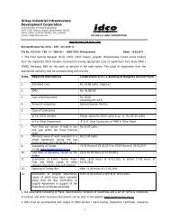
ORISSA INDUSTRIAL INFRASTRUCTURE DEVELOPMENT CORPORATION (<strong>IDCO</strong>)<br />
<strong>IDCO</strong> TOWER JANPATH, BHUBANESWAR- 751022<br />
(<strong>IDCO</strong>/QP/ELECT/F-05)<br />
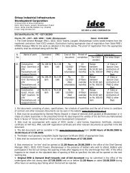
TENDER CALL NOTICE<br />
No. BBSR / ELECT / E - 1550 / 09 - 10 / 185 Dated. 29.01.2010<br />
1. The Divisional Head, Electrical Division, <strong>IDCO</strong>, Bhubaneswar invites Sealed <strong>Tender</strong>s from HV Airconditioning<br />
Manufacturers / Experienced HV A.C. Contractors <strong>for</strong> <strong>Supply</strong>, <strong>Erection</strong>, <strong>Testing</strong><br />
<strong>and</strong> Commissioning of HV Air-Conditioning system with Scroll Chillers of (48x3)TR<br />
(approx.) along with associated works <strong>for</strong> MCA Building at Plot No. 9 (P), Markat Nagar,<br />
Sector - 1, Bidanasi, Cuttack as per brief details indicated in the table below. The <strong>Tender</strong><br />
Documents will be issued to the firms on production of following satisfactory documents only.<br />
Documents as Original Manufacturer or as experienced AC Contractors having executed similar<br />
nature of works in a single order value not less than Rs.70.00 Lakh within last Three Years.<br />
Copy of valid VAT Registration <strong>and</strong> Clearance Certificate.<br />
Copy of valid PAN.<br />
Copy of EPF Registration Certificate.<br />
Documents in support of having Service Facilities at Cuttack <strong>and</strong> Bhubaneswar.<br />
2. Bids must be accompanied by Earnest Money in the shape of Dem<strong>and</strong> Draft from any<br />
Nationalised Bank <strong>for</strong> an amount as mentioned in the table payable at Bhubaneswar <strong>and</strong> drawn<br />
in favour of “Orissa Industrial Infrastructure Development Corporation”. Bids without required<br />
amount of Earnest Money will not be taken in to consideration.<br />
3. The <strong>Tender</strong> Document can also be downloaded within 02.02.10 to 10.02.10 from our Website at<br />
www.idco.in, in that case the cost of the Bid Document shall be submitted along with the <strong>Tender</strong><br />
in the <strong>for</strong>m of Dem<strong>and</strong> Draft drawn in favour of “Orissa Industrial Infrastructure Development<br />
Corporation” payable at Bhubaneswar. The offer shall be considered only if the authority is<br />
satisfied about the fulfillment of eligibility criteria by the firm. <strong>IDCO</strong> shall not be responsible <strong>for</strong> any<br />
delay / difficulty / inaccessibility of the Downloading facility, incase of any discrepancy between<br />
the <strong>Tender</strong> Document Downloaded <strong>and</strong> the Master Copy available in the office, the master copy<br />
will prevail, No claim on this account will be entertained.<br />
4. The sealed bids must be delivered to Divisional Head (Electrical), <strong>IDCO</strong>, <strong>IDCO</strong> Towers, Janpath,<br />
Bhubaneswar - 751022, Orissa office on or be<strong>for</strong>e 15.00 Hrs. on 16.02.10 either by Regd. Post /<br />
Speed Post. The Bids will be opened on 17.02.10 at 16.00 Hrs. in presence of the bidders or their<br />
authorized representatives, who wishes to attend. If the office happens to be eventually closed on<br />
the date of submission of the bids, the bids will be received / opened on the next working day of<br />
opening of the office at the same time <strong>and</strong> venue. However, the undersigned will not be held<br />
responsible <strong>for</strong> any postal delay. Other details can be seen in the Bidding Documents.
5. The authority reserves the right to accept or reject any or all the bids or parts without<br />
assigning any reason there of.<br />
6. In case of any clarification visit of site the bidders can contact Sri M.Amiya, Joint Manager<br />
(Electrical), <strong>IDCO</strong>, Bhubaneswar at Tel. No. (0674) 25411819 - Extn. 456 during office hours.<br />
TABLE<br />
Sl.<br />
No<br />
Name of the Work<br />
Approx<br />
Value<br />
of Work<br />
Bid<br />
Security<br />
(in Rs.)<br />
Cost of<br />
Bid<br />
Document<br />
(in Rs.)<br />
Stipulated<br />
Period of<br />
Completion<br />
1. <strong>Supply</strong>, <strong>Erection</strong>, <strong>Testing</strong> <strong>and</strong><br />
93.32<br />
1 % of<br />
10,000.00<br />
Ninety<br />
Commissioning of HV Air-<br />
Lakh<br />
the<br />
+ VAT<br />
Days<br />
Conditioning system with Scroll<br />
Quoted<br />
Chillers <strong>for</strong> (48x3)TR (approx.) along<br />
Value<br />
with associated works <strong>for</strong> MCA<br />
Building at Plot No. 9 (P), Markat<br />
Nagar, Sector-1, Bidanasi, Cuttack.<br />
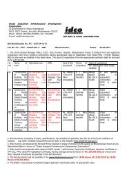
Memo No. 186 / Dtd.29.01.2010<br />
Sd/-<br />
Divisional Head (Electrical)<br />
Copy submitted to Chief General Manager (Civil), <strong>IDCO</strong>, Bhubaneswar <strong>for</strong> kind in<strong>for</strong>mation.<br />
Memo No. 187 / Dtd.29.01.2010<br />
Sd/-<br />
Divisional Head (Electrical)<br />
Copy to DGM (MIS), <strong>IDCO</strong>, Bhubaneswar <strong>for</strong> in<strong>for</strong>mation <strong>and</strong> necessary action. The copy of <strong>Tender</strong><br />
Notice <strong>and</strong> Bid Document contained in the Soft Copy enclosed may be included in our Website.<br />
Memo No. 188 / Dtd.29.01.2010<br />
Sd/-<br />
Divisional Head (Electrical)<br />
Copy to Manager (PR) <strong>for</strong> favour of kind in<strong>for</strong>mation <strong>and</strong> necessary action as due. The enclosed<br />
short <strong>for</strong>m of the <strong>Tender</strong> Notice may be published in News Papers as per norms. <strong>Tender</strong> Notice may<br />
be published on or be<strong>for</strong>e 02.02.2010.<br />
Memo No. 189 / Dtd.29.01.2010<br />
Copy to <strong>IDCO</strong> Notice Board <strong>for</strong> wide circulation.<br />
Sd/-<br />
Divisional Head (Electrical)<br />
Sd/-.<br />
Divisional Head (Electrical)<br />
Memo No. 190 / Dtd.29.01.2010<br />
Copy to Divisional Head, Cuttack Division, <strong>IDCO</strong>, Cuttack <strong>for</strong> in<strong>for</strong>mation.<br />
Sd/-<br />
Divisional Head (Electrical)
COMMERCIAL TERMS & CONDITIONS<br />
The Bidder shall tabulate the commercial terms <strong>and</strong> conditions of the tender in the following.<br />
Additional sheets may be attached, if required.<br />
1.0 Bidder’s Complete Company Name :<br />
2.0 Bidder’s Proposal Number :<br />
3.0 Bidder’s Proposal Date :<br />
4.0 Name <strong>and</strong> Designation of the Officer of the Bidder<br />
to whom all references shall be made <strong>for</strong><br />
expeditious technical co-ordination<br />
:<br />
5.0 Bidder’s Proposal Validity<br />
a) Is the Bidder’s Proposal validity as per Owner’s<br />
<strong>Specification</strong> acceptable?<br />
b) If not, specify the terms of Validity of Bidder’s<br />
Proposal (in months) from the Date of Opening of<br />
Price Bid<br />
: (Yes / No)<br />
:<br />
6.0 Delivery <strong>and</strong> Completion<br />
a) Is the term of Delivery / Completion Period as per<br />
Owner’s <strong>Specification</strong> Acceptable?<br />
b) If not, specify the Terms of Delivery / Completion<br />
Period (in months) from the date of issue of Letter<br />
of Intent<br />
: (Yes / No)<br />
:<br />
i) <strong>Supply</strong> of Material (Delivery) :<br />
ii) Installation, <strong>Testing</strong> <strong>and</strong> Commissioning of<br />
works complete in all respect. (Completion)<br />
c) Whether the Delivery / Completion Period is<br />
Guaranteed under Penalty / Liquidated Damage<br />
as per GCC?<br />
:<br />
: (Yes / No)<br />
7.0 Terms of Payment<br />
a) Are Terms of Payment as per Owner’s<br />
<strong>Specification</strong> Acceptable?<br />
: (Yes / No)<br />
b) If not, specify the Terms of Payment :<br />
8.0 Whether EMD Deposited? : (Yes / No)<br />
If so, give reference. :<br />
If not, give reasons. :
9.0 Whether Registered with D.G.S. & D / E.P.M. /<br />
Any other such Organisation?<br />
If so, Give Details? (Enclose Photostat Copy of<br />
the reference letter)<br />
: (Yes / No)<br />
:<br />
10.0 Whether Photocopy of following currently valid<br />
documents furnished?<br />
(a) Orissa Sales Tax Registration Certificate : (Yes / No)<br />
(b) Orissa Sales Tax Clearance Certificate : (Yes / No)<br />
(c) Income Tax Clearance Certificate : (Yes / No)<br />
(d) Provident Fund Registration Certificate : (Yes / No)<br />
11.0 Con<strong>for</strong>mance<br />
a) Whether the materials offered are strictly in<br />
accordance with owner’s specification?<br />
: (Yes / No)<br />
b) If not, have deviation sheets been duly filled up? : (Yes / No)<br />
12.0 Is the Per<strong>for</strong>mance Guarantee Period specified in<br />
GCC accepted?<br />
: (Yes / No)<br />
If not, specify the Per<strong>for</strong>mance Guarantee Period<br />
(in months)<br />
a) From the date of Commissioning at Site :<br />
b) From the date of Despatch :<br />
13.0. Whether after Sales Service facilities are<br />
available at Cuttack / Bhubaneswar<br />
: (Yes / No)<br />
a) If Yes, give Address <strong>and</strong> Details<br />
b) If No, location Nearest Service Centre<br />
14.0. Whether <strong>Tender</strong>er is a Manufacturer of Approved<br />
make of Materials?<br />
: (Yes / No)
GUIDELINES ON BANK GUARANTEE<br />
The following points are required to be noted by the party while submitting any Bank<br />
Guarantee.<br />
1. Non-judicial stamp papers on which Bank Guarantee is typed must be purchased in the name<br />
of the issuing Bank.<br />
2. The Bank Guarantee must be executed on non-judicial stamp paper of the value applicable in<br />
the State, where the Bank Guarantee has been executed.<br />
3. The Bank Guarantee must be furnished in the given pro<strong>for</strong>ma by any Nationalised Bank <strong>and</strong><br />
made operable at Bhubaneswar only.<br />
4. The Bank Guarantee must be executed within six months from the date of purchase of nonjudicial<br />
stamp papers.<br />
5. The Bank Guarantee should never be typed on both sides of the non-judicial stamp papers.<br />
6. The Bank Officer executing the Bank Guarantee must furnish the number <strong>and</strong> date of power<br />
of Attorney / Delegation of Authority by which, he has been authorised to issue the Bank<br />
Guarantee.<br />
7. The person executing the Bank Guarantee must write his full name <strong>and</strong> designation.<br />
8. The person, executing the Bank Guarantee, must sign in all pages of Bank Guarantee.<br />
9. All cuttings / additions / over writings in inks must be authenticated by the person executing<br />
the Bank Guarantee by his signature <strong>and</strong> seal of the Bank.<br />
10. Execution of Bank Guarantee must be witnessed by two persons.<br />
11. Witnesses must mention their full name <strong>and</strong> address.<br />
12. Three months time must be given to file claim or suit from the date of expiry of the Bank<br />
Guarantee.<br />
13. The Act, under which issuing Bank is constituted, should be correctly given.<br />
14. If EMD is deposited in shape of Bank Guarantee, it should be valid, operative <strong>and</strong><br />
irrecoverable till 60 (sixty days) after the validity of offer.<br />
15. All dates should be carefully <strong>and</strong> correctly put in the Bank Guarantee.
SECTION - 1<br />
(Formats & Deviations)<br />
FORMAT FOR BANK GUARANTEE AS EMD<br />
Ref. No.<br />
Dated<br />
Bank Guarantee No.<br />
To<br />
M/s. Orissa Industrial Infrastructure Development Corporation,<br />
<strong>IDCO</strong>, <strong>IDCO</strong> Towers, Janpath,<br />
Bhubaneswar - 751022,<br />
Dist. Khurda (Orissa)<br />
Dear Sirs,<br />
In consideration of Orissa Industrial Infrastructure Development Corporation, having its<br />
Registered Office at <strong>IDCO</strong> Towers, Janpath, Bhubaneswar (hereinafter called the ‘Owner’<br />
which expression shall unless repugnant to the subject or context include its successors <strong>and</strong><br />
assigns) having issued Notice Inviting <strong>Tender</strong> <strong>for</strong> “<strong>Supply</strong>, <strong>Erection</strong>, <strong>Testing</strong> <strong>and</strong><br />
Commissioning of HV Air-Conditioning system with Scroll Chillers <strong>for</strong> (48x3)TR<br />
(approx.) along with associated works <strong>for</strong> MCA Building at Plot No. 9 (P), Markat Nagar,<br />
Sector-1, Bidanasi, Cuttack” <strong>and</strong> M/s. having its<br />
Registered Head Office at<br />
(hereinafter called the ‘<strong>Tender</strong>er’) who<br />
wished to participate in the said tender <strong>for</strong> “<strong>Supply</strong>, <strong>Erection</strong>, <strong>Testing</strong> <strong>and</strong> Commissioning<br />
of HV Air-Conditioning system with Scroll Chillers <strong>for</strong> (48x3)TR (approx.) along with<br />
associated works <strong>for</strong> MCA Building at Plot No. 9 (P), Markat Nagar, Sector-1, Bidanasi,<br />
Cuttack” <strong>and</strong> the owner, as a special favour, have agreed to accept an irrevocable <strong>and</strong><br />
unconditional Bank Bid Guarantee executed by any Nationalised Bank operable at its<br />
Bhubaneswar Branch only <strong>for</strong> an amount of Rs.<br />
valid up to<br />
on behalf of the tenderer in lieu of Cash Deposit required to be made by the<br />
<strong>Tender</strong>er, as a condition precedent <strong>for</strong> participation in the said tender.<br />
We the (Bank & Address) incorporated under law <strong>and</strong> having our<br />
Registered Head Office at<br />
<strong>and</strong> one of our branches at<br />
(Bhubaneswar Branch Address) do hereby unconditionally <strong>and</strong> irrevocably guarantee <strong>and</strong><br />
undertake to pay to the ‘Owner’ immediately on dem<strong>and</strong> at our Bhubaneswar Branch without<br />
any demur reservation, protest, contest <strong>and</strong> recourse to the extent of the said sum of<br />
Rs. (Rupees ) only.<br />
Any such claim/ dem<strong>and</strong> made by the said ‘Owner’ on us shall be conclusive <strong>and</strong> binding on<br />
us irrespective of any dispute or differences raised by the tenderer. This guarantee shall be<br />
irrevocable <strong>and</strong> shall remain valid up to . If any further extension of this guarantee is<br />
required, the same shall be extended to such required period on receiving instruction from<br />
the <strong>Tender</strong>er on whose behalf this guarantee is issued.
We, the said Bank, lastly undertake not to revoke this guarantee during its currency<br />
except with the previous consent of the Owner in writing <strong>and</strong> agree that any change in the<br />
constitution of the said tenderer or the said Bank shall not discharge our liability here under.<br />
I witness where of, the Bank, through its authorised offices has set its h<strong>and</strong> <strong>and</strong><br />
stamp on this day of 2010 at .<br />
Witness :<br />
Signature<br />
(Signature)<br />
Name : Name :<br />
Designation with Bank Stamp.<br />
Official Address :<br />
Attorney as per power of<br />
Attorney No.<br />
Date.<br />
Note : The stamp papers of Rupees <strong>for</strong>ty only shall be purchased in the name of “Bid<br />
Guarantee issuing Bank”.
DEVIATION SHEET: PART - A<br />
If the proposal has got any deviation from the Technical <strong>Specification</strong>, the Bidder shall<br />
tabulate these deviations clause by clause in this Schedule. Additional sheets may be<br />
attached, if required.<br />
Clause No.<br />
Deviations
DEVIATION SHEET : PART - B<br />
If the proposal has got any deviation from the tendering conditions <strong>and</strong> the General<br />
Conditions of Contract, the Bidder shall tabulate these deviations clause by clause in this<br />
Schedule. Additional sheets may be attached, if required.<br />
Clause No.<br />
Deviations
DEVIATION SHEET (IN PRICE): PART - C<br />
Against each <strong>and</strong> every deviation from the Technical <strong>Specification</strong> as enumerated in<br />
Deviation Sheet: Part - A, the amount by which the Bid Price will thereby be increased or decreased<br />
shall be intimated clause by clause in this Schedule. In case the amount is not mentioned in the<br />
Schedule against any of the deviations mentioned in Deviation Sheet: Part - A, it will be taken <strong>for</strong><br />
granted that the same does not involve any change in the Bid Price. Additional sheets may be<br />
attached, if required.<br />
Clause No. Deviation if any Amount by which the Bid Price will change<br />
Increase (Rs.)<br />
Decrease (Rs.)
INSTRUCTION FOR THE TENDERER<br />
General Instructions:<br />
The work put to tender pertains to “<strong>Supply</strong>, <strong>Erection</strong>, <strong>Testing</strong> <strong>and</strong> Commissioning of HV<br />
Air-Conditioning system with Scroll Chillers <strong>for</strong> (48x3)TR (approx.) along with associated<br />
works <strong>for</strong> MCA Building at Plot No. 9 (P), Markat Nagar, Sector-1, Bidanasi, Cuttack”. The<br />
tenderer shall ensure to follow the instructions given hereunder failing which the tenders shall be<br />
liable <strong>for</strong> rejection.<br />
Scope of Proposal:<br />
The scope of proposal shall be in accordance with the enclosed technical specification<br />
covering Design, supply of materials at site, labour <strong>for</strong> erection, testing <strong>and</strong> commissioning of <strong>Supply</strong>,<br />
<strong>Erection</strong>, <strong>Testing</strong> <strong>and</strong> Commissioning of HV Air-Conditioning system with Scroll Chillers <strong>for</strong><br />
(48x3)TR (approx.) along with associated works <strong>for</strong> MCA Building at Plot No. 9(P), Markat<br />
Nagar, Sector-1, Bidanasi, Cuttack on turnkey basis complete in all respect, obtaining clearance<br />
<strong>and</strong> final h<strong>and</strong>ing over to <strong>IDCO</strong> authorities.<br />
Submission of <strong>Tender</strong>:<br />
<strong>Tender</strong>ers are advised to fill up the prices only in the prescribed <strong>for</strong>mat given by <strong>IDCO</strong>. The<br />
tender shall be submitted in two parts, each part being sealed in separate envelope.<br />
Part I will cover the Technical Bid with required drawings; general conditions special conditions,<br />
deviations if any <strong>and</strong> EMD. Sales Tax Clearance Certificate, PAN, VAT Registration Certificate, Past<br />
Experience.<br />
Part II will cover only the Price Bid,<br />
Each envelope shall be duly sealed <strong>and</strong> super-scribed with ‘Techno-Commercial Bid’ <strong>and</strong><br />
‘Price Bid’ respectively. All the two envelopes shall be put inside another envelope, super-scribed with<br />
“<strong>Supply</strong>, <strong>Erection</strong>, <strong>Testing</strong> <strong>and</strong> Commissioning of HV Air-Conditioning system with Scroll<br />
Chillers <strong>for</strong> (48x3)TR (approx.) along with associated works <strong>for</strong> MCA Building at Plot No. 9(P),<br />
Markat Nagar, Sector -1, Bidanasi, Cuttack” <strong>and</strong> sealed properly. The Techno-Commercial Bid<br />
<strong>and</strong> EMD in Part I shall be opened on the due date of opening mentioned in tender call notice.<br />
<strong>Tender</strong>ers may be called to participate in techno-commercial discussions/ negotiations <strong>for</strong> finalisation<br />
of technical bid. The price bid shall be opened after finalisation of technical bid. Telegraphic tenders<br />
will not be accepted.<br />
Receipt <strong>and</strong> Opening of <strong>Tender</strong>:<br />
<strong>Tender</strong>s as described above shall be received in the Office of the Divisional Head (Electrical),<br />
<strong>IDCO</strong>, <strong>IDCO</strong> Towers, Janpath, Bhubaneswar - 751022 <strong>and</strong> shall be opened on the scheduled date<br />
<strong>and</strong> time. Telegraphic <strong>Tender</strong>s will not be Accepted.<br />
Prices:<br />
The tenderer shall ensure that all prices are filled in the price schedule both in words <strong>and</strong><br />
figures. No overwriting shall be allowed. The tenderer shall countersign all scoring <strong>and</strong> cancellation.<br />
In case of illegibility, the interpretation <strong>and</strong> decision of the Engineer-in-charge of the work shall be<br />
final.
All entry shall be in English language only. The price should be inclusive of all taxes, duties<br />
<strong>and</strong> transit insurance <strong>and</strong> FOR destination. Please note that this office will not issue any concessional<br />
<strong>for</strong>m <strong>for</strong> sales tax. The Purchaser shall not issue any Way Bill.<br />
In case if on check, there are differences between the rate given by the bidder in words <strong>and</strong><br />
figures or in the amounts worked out by him, the following procedure shall be followed.<br />
When there is difference between a rate in figure <strong>and</strong> in words, the rate that corresponds to<br />
the amount worked out by the bidder shall be taken as correct.<br />
When the bidder has not worked out the amount of an item or it does neither correspond with<br />
the rate written in figures nor in words, then rate quoted by the bidder in words shall be taken<br />
as correct.<br />
When the rate quoted by the bidder in figures <strong>and</strong> in words tallies but the amount is not<br />
worked out correctly, the rates quoted by the bidder shall be taken as correct <strong>and</strong> not the<br />
amount.<br />
Sales Tax <strong>and</strong> Income Tax Clearance:<br />
The tenderer shall furnish valid current Sales Tax Clearance Certificates, Sales Tax<br />
Registration Number (TIN / SRIN) <strong>and</strong> ITCC / PAN along with EMD contained in the envelope.<br />
<strong>Tender</strong>s not accompanied with these documents shall be liable <strong>for</strong> rejection at the discretion of the<br />
purchaser.<br />
Nature of Contract:<br />
The work put to tender as described “scope of proposal” being a job contract in nature shall<br />
be treated as “Indivisible” works contract. There<strong>for</strong>e this contract shall be subject to “Orissa Sales Tax<br />
on works contract”.<br />
Validity:<br />
The <strong>Tender</strong>ers shall keep the tender valid <strong>for</strong> a period of 180 (One Hundred Eighty) days<br />
from the date of Opening of Price Bid.<br />
Reservation of Right:<br />
The owner reserves the right to accept any bid or reject any or all bids or cancel or withdraw<br />
invitation <strong>for</strong> bid without assigning any reason <strong>for</strong> such decision. Such decision, by the owner shall<br />
not be subject to question by any bidder <strong>and</strong> the owner shall bear no liability whatsoever consequent<br />
upon such a decision.<br />
Clarifications on <strong>Tender</strong> <strong>Specification</strong>s:<br />
The tenderer should seek <strong>for</strong> the clarifications with regard to the specification, if any, be<strong>for</strong>e<br />
submission of the tenders. No correspondence on this account will be entertained after submission of<br />
tender.
GENERAL TERMS AND CONDITIONS OF CONTRACT FOR TURNKEY CONTRACT<br />
Definition of Terms:<br />
In construing this contract <strong>and</strong> the scope of work, the following words will have same<br />
meaning herein assigned to them unless there is something in the subject or context in consistent<br />
with such construction.<br />
Owner:<br />
The “Owner” shall mean the Orissa Industrial Infrastructure Development Corporation (<strong>IDCO</strong>)<br />
(A Government of Orissa Undertaking) <strong>and</strong> shall include its legal representatives, successors <strong>and</strong><br />
assignees.<br />
Contractor:<br />
The “Contractor” shall mean the firm whose tender has been accepted by the owner <strong>and</strong><br />
shall include its legal representatives, successors <strong>and</strong> assignees.<br />
Engineer In Charge:<br />
The “Engineer-in-charge” shall mean the Divisional Head (Electrical) <strong>IDCO</strong>, Electrical<br />
Division, First Floor, <strong>IDCO</strong> Towers, Janpath, Bhubaneswar or his authorised representative.<br />
Consulting Engineer:<br />
The “Consulting Engineer” shall mean the Divisional Head (Electrical), <strong>IDCO</strong>, <strong>IDCO</strong> Towers,<br />
Janpath, Bhubaneswar or his authorised representative.<br />
Consignee:<br />
The “Consignee” shall mean the person authorised by the Consulting Engineer / Engineer-incharge<br />
to receive the materials, supervise <strong>and</strong> take measurement of the work.<br />
Site:<br />
The “Site” shall mean, the actual place of the proposed Project as detailed in the specification<br />
or other place where work has to be executed under this contract.<br />
<strong>Specification</strong>:<br />
The “<strong>Specification</strong>” shall mean collectively all terms stipulated in the contract known as<br />
General Conditions, Technical <strong>Specification</strong> <strong>and</strong> such amendments as may be made in the<br />
Agreement pertaining to method <strong>and</strong> manner of per<strong>for</strong>ming the work with respect of quantities &<br />
qualities of materials <strong>and</strong> workmanship to be furnished under the contract.<br />
Contract:<br />
The “Contract” shall mean <strong>and</strong> include the following documents:<br />
(a) Invitation to <strong>Tender</strong><br />
(b) Instructions to <strong>Tender</strong>er<br />
(c) General Terms <strong>and</strong> Conditions of Contract
(d) Technical <strong>Specification</strong><br />
(e) Contract Agreement<br />
(f) Contractors’ tender proposal including clarification letters<br />
(g) Letter of Intend<br />
(h) Work order<br />
(i) Agreement<br />
Commissioning:<br />
The “Commissioning” shall mean the first authorised operation of the equipment / installation<br />
after completion of erection, testing, initial adjustments, statutory approvals etc.<br />
Approved:<br />
The “Approved” shall mean the written approval of the Consulting Engineer / Engr-in-charge.<br />
Months:<br />
Months shall mean the calendar month.<br />
Per<strong>for</strong>mance Test:<br />
The “Per<strong>for</strong>mance Test” shall mean all the tests as prescribed in the specification / ISS to be<br />
carried out by the contractor be<strong>for</strong>e taking over the installation by the owner.<br />
Final Acceptance:<br />
The “Final Acceptance” shall mean the owners written acceptance of the works per<strong>for</strong>med<br />
under the contract after successful completion of Per<strong>for</strong>mance & Guarantee Test <strong>and</strong><br />
Commissioning.<br />
Contractor to In<strong>for</strong>m Himself Fully:<br />
The contractor shall be deemed to have carefully examined the General Conditions,<br />
<strong>Specification</strong>s, Schedules <strong>and</strong> Drawings <strong>and</strong> also to have satisfied himself as to the nature <strong>and</strong> type<br />
of work to be executed <strong>and</strong> where necessary of the site conditions <strong>and</strong> other relevant matters <strong>and</strong><br />
details. Any in<strong>for</strong>mation thus had or otherwise obtained from the owner / consulting engineer or the<br />
inspector shall not in any way relieve the contractor from his responsibility <strong>for</strong> supplying the plant <strong>and</strong><br />
equipment or material <strong>and</strong> executing the work in terms of the specification including all details <strong>and</strong><br />
incidental works <strong>and</strong> supply of all accessories or apparatus which may not have been specifically<br />
mentioned in the specification or drawings but otherwise necessary <strong>for</strong> ensuring complete erection<br />
<strong>and</strong> safe <strong>and</strong> sufficient working of the plant <strong>and</strong> equipment or installation.<br />
Deviation:<br />
The contractor must get the sample materials, which are under scope of supply of contractor,<br />
approved by the Client <strong>and</strong> Engineer-in-charge be<strong>for</strong>e procurement otherwise the same shall be<br />
liable <strong>for</strong> rejection.
In case the tenderer wish to deviate in any way from the General Conditions of contract or the<br />
Technical <strong>Specification</strong>s, he should draw specific attention to such departure in his tender. All such<br />
deviations shall be clearly mentioned in the Deviation Sheet giving the corresponding reference<br />
clause Number. Terms such as See covering letter or <strong>Tender</strong> printed General Terms <strong>and</strong> Condition<br />
are not acceptable, unless such deviations are submitted with the tender, it will be understood <strong>and</strong><br />
agreed that the <strong>Tender</strong>ers proposal is based on strict con<strong>for</strong>mance to purchasers specification in all<br />
respects.<br />
Price:<br />
i. The unit rates quoted <strong>for</strong> design, engineering manufacturing supply at site, storage, h<strong>and</strong>ling<br />
installation, testing <strong>and</strong> commissioning shall be inclusive of all taxes, duties, royalties <strong>and</strong> all<br />
other taxes applicable such as sales tax on work contract <strong>and</strong> income tax etc.<br />
ii. The prices are to be quoted on the lump-sum price based on item rates as indicated in the<br />
specification. THE TENDERER SHALL QUOTE FIRM PRICES FOR THE COMPLETE SCOPE OF WORK.<br />
The prices are to be quoted <strong>for</strong> the work complete in all respects in strict accordance with the<br />
specifications. Should the <strong>Tender</strong>er wish to propose alternatives the same should be clearly<br />
mentioned in the deviation. Any action on the part of the <strong>Tender</strong>er to revise the price/ prices/<br />
<strong>and</strong>/ or to change the structure of price / prices at his own instance after opening of the<br />
tender may result in rejection of the tender.<br />
Terms of Payment:<br />
Subject to any deduction which the owner may be authorised to make under the contract, the<br />
contractor shall on the certificate of the engineer or his authorised representatives whose certificate<br />
will be final regarding evidence of materials at site <strong>and</strong> completion or erection etc. be entitled to<br />
payments generally as follows;<br />
70% of the contract price shall be paid after supply of materials, verification <strong>and</strong><br />
acceptance of materials at site in good condition by the Consignee / Engineer - in -charge <strong>and</strong><br />
presentation of bills, subject to acceptance of your Security Deposit B.G. <strong>and</strong> execution of agreement.<br />
20% shall be paid after completion of erection <strong>and</strong> testing of the work.<br />
Balance 10% shall be paid on completion of satisfactory Commissioning, Per<strong>for</strong>mance<br />
Test <strong>and</strong> after final acceptance by the Engineer-in-charge, subject to you submission of Per<strong>for</strong>mance<br />
B.G. <strong>and</strong> acceptance thereof.<br />
Contract Price:<br />
The lump sum price quoted by the contractor in his bid with additions <strong>and</strong> deletion as may be<br />
agreed be<strong>for</strong>e signing of the contract <strong>for</strong> the entire scope of the work viz. <strong>Supply</strong> <strong>and</strong> erection of<br />
equipment concerned under the specification <strong>and</strong> documents shall be treated as the contract price.<br />
Change of Quantity:<br />
The owner reserves the right to vary the quantities of items or groups of items to be ordered<br />
as specified in the accompanying Technical <strong>Specification</strong>s as may be necessary during the execution<br />
of the contract.
Taxes:<br />
i. The contractor shall include all taxes, duties, royalty of whatever nature, entry tax; other local<br />
taxes etc. if any in the quoted price.<br />
ii. Sales tax or any other tax on materials required <strong>for</strong> the work <strong>and</strong> also tax on works contract<br />
shall be payable by the contractor. Owner will not entertain any such claim whatsoever on<br />
this account.<br />
iii. Not with st<strong>and</strong>ing anything contained elsewhere in the contractor the owner shall deduct at<br />
source from the payment due to the contract, the taxes as required under Orissa Sales Tax<br />
Act <strong>and</strong> Income Tax Act, 1961 or as amended from time to time, or any other statute. The<br />
owner shall pay the amount so deducted to the Sales Tax <strong>and</strong> Income Tax authorities as per<br />
the law. This is <strong>for</strong> the contractor to deal with the Sales tax Authority directly in respect to any<br />
claim or refund relating to the above tax owner shall not be liable or responsible <strong>for</strong> any type<br />
of payment <strong>for</strong> reimbursement in this regard.<br />
iv. The supplier / contractor should furnish his valid STCC with OVAT Registration Number.<br />
Liquidated Damage <strong>for</strong> Delay in Completion:<br />
If the contractor fails in the due per<strong>for</strong>mance of the contract to supply/ erection/ testing /<br />
commissioning the equipment within the time fixed by the owner or any extension thereof, he shall be<br />
liable at the discretion of the Engineer to liquidated damage amounting to 0.5% (HALF PERCENT) of the<br />
Contract Price per Week. The contractor’s liability <strong>for</strong> delay shall not in any case exceed 5% (FIVE<br />
PERCENT) of the total contract price. If the contractor shall fail to supply the equipment or any part<br />
thereof within a reasonable period after the expiry of the appointed time of extended time as may be<br />
provided <strong>for</strong> in the contract the provisions in clause " Negligence " shall become operative, in addition<br />
to the liability of Liquidated Damage as above.<br />
Despatch Instructions:<br />
The materials that will be required to be despatched under this contract, shall be despatched<br />
to the work site in the name of the Consignee with a copy addressed to MCA Building at Plot No. 9<br />
(P), Markat Nagar, Sector-1, Bidanasi, Cuttack. The contractor shall have to intimate the probable<br />
date of arrival of materials at site to the Engineer.<br />
Inspection <strong>and</strong> Tests:<br />
The corporation shall inspect, examine <strong>and</strong> test the equipment material through its<br />
representative at the manufacture/ suppliers works during or after the manufacture of goods prior to<br />
despatch on receipt of a clear notice of minimum two weeks in advance to the reckoned from the date<br />
of receipt by the purchase. The supplier/ contractor shall provide all facilities as may be required to<br />
carry out the tests in accordance with approved st<strong>and</strong>ards free of cost.
Negligence:<br />
If the contractor neglects to execute the work with due diligence <strong>and</strong> expedition of refuse or<br />
neglects to comply with any reasonable orders given to him in writing by the Engineer in connection<br />
with the work, or contravene the provisions of the contract, the purchaser may give notice in writing to<br />
the contractor calling upon him to make good the failure, neglect or contravention complained of.<br />
Should the contractor fail to comply with such notice within a period, in the case of failure, neglect or<br />
contravention capable of being made good within that time or otherwise within such time as may in<br />
the opinion of the purchaser be reasonably necessary <strong>for</strong> making it good, then <strong>and</strong> in such case the<br />
purchaser shall have the option <strong>and</strong> be at liberty to take the work wholly or in part, out of the<br />
contractors h<strong>and</strong> <strong>and</strong> may carry on the work envisaged in the contract at a price with any other<br />
materials, tools, tackle or labour <strong>for</strong> the purpose of completing the works or part thereof. In such event<br />
the purchaser shall without being responsible to the contractor <strong>for</strong> fair wear <strong>and</strong> tear of the same be<br />
entitled to seize <strong>and</strong> take possession <strong>and</strong> have free use of all materials, tools tackle or other things<br />
which may be on the site, <strong>for</strong> use at any time in connection with the work to the exclusion of any right<br />
of the contractor over the same <strong>and</strong> the purchaser shall be entitled to apply <strong>and</strong> balance sum which<br />
may otherwise be then due on the contract by him to the contractor or such part thereof as may be<br />
necessary. If the cost of executing the work as a<strong>for</strong>esaid shall exceed the balance due to the<br />
contractor fails to make good the deficit, the said materials, tools tackle, construction plant or other<br />
things, the property of the contractor as may not have been used up in the completion of the works,<br />
may be sold by the purchaser <strong>and</strong> the proceeds applied towards the payment of such sale. Any<br />
outst<strong>and</strong>ing balance existing after crediting the proceeds of such sale shall be paid by the contractor<br />
on the certificate of the Engineer, but when all expenses, cost <strong>and</strong> charges incurred in the completion<br />
of the work are paid by the contractor, all such materials, tools tackle, construction plant or other<br />
things not used up in the completion of the works <strong>and</strong> remaining unsold shall be removed by the<br />
contractors. If the proceeds of the above sale of the contractors materials tools <strong>and</strong> tackle,<br />
construction plant etc. are insufficient to cover the executing the a<strong>for</strong>esaid work, the balance<br />
remaining after crediting the proceeds of such sale shall be recoverable from the contractor by<br />
encasing the Bank Guarantee available/ any other money payable by the purchase or by action of<br />
law.<br />
Notwithst<strong>and</strong>ing anything contained above, the purchaser may determine the contract due to<br />
any breach of failure of the contract, without notice be<strong>for</strong>e determining the contract as above, if in the<br />
opinion of the purchaser, the default or defaults committed by the contractor is/ are curable <strong>and</strong> can<br />
be cured by the contractor if an opportunity is given to him, then the owner may issue a notice in<br />
writing calling upon the contractor or default within such time as may be specified in the notice.<br />
If the cost of executing the work as a<strong>for</strong>esaid shall exceed the balance due to the contractor<br />
fails to make good the deficit, the said materials, tools, tackle, construction plant or other things, the<br />
property of the contractor as may not have been used up in the completion of the work, may be sold<br />
by the purchaser <strong>and</strong> the proceeds applied towards the payment of such sale. Any outst<strong>and</strong>ing<br />
balance existing after crediting the proceeds of such sale shall be paid by the contractor on the<br />
certificate of the Engineer, but when all expenses, costs <strong>and</strong> charges incurred in the completion of the<br />
work are paid by the contractor, all such materials, tools, tackle, construction plant or other things not<br />
used up in the completion of the works <strong>and</strong> remaining unsold shall be removed by the contractor.
If the proceeds of the above sale of the contractor's materials, tools, tackle, construction plant<br />
etc. are insufficient to cover executing the a<strong>for</strong>esaid work, the balance remaining after crediting the<br />
proceeds of such sale shall be recoverable from he contractor by encasing the bank Guarantee<br />
available/ any other money payable by purchaser or by action of law.<br />
Notwithst<strong>and</strong>ing anything contained above, the purchaser may determine the contract due to<br />
any breach of failure of the contract, without notice be<strong>for</strong>e determining the contract as above, if in the<br />
opinion of the purchaser, the default or defaults committed by the contractor is / are curable <strong>and</strong> can<br />
be cured by the contractor if an opportunity is given to him, then the owner may issue a notice in<br />
writing upon the contractor to cure the default within such time as may be due in the event of<br />
termination, the security deposit will be <strong>for</strong>feited without reference to the contractor <strong>and</strong> if no amount<br />
is available towards security deposit, an identical amount is recoverable from the contractor.<br />
Power to Vary or Omit Work:<br />
No alternation, amendments, omissions, additions or variations of the work herein after<br />
referred to as variations, under the contract shall be made by the contract except as directed in<br />
writing by the Engineer, but the engineer shall have full power, subject to the provision hereinafter<br />
contained from time to time during the execution of the contract by notice in writing, to instruct t the<br />
contractor shall carry out such variations <strong>and</strong> be bound by the same conditions as far as applicable,<br />
as through the said clarifications occurred in the contract, if any suggested variations would , in the<br />
opinion of the contractor, if carried our, percent him from fulfilling any of his obligations or guarantees<br />
under the contract, he shall notify the Engineer thereof within 10 days in writing <strong>and</strong> the Engineer<br />
con<strong>for</strong>ms his instructions, the contractor’s obligations <strong>and</strong> guarantees shall be modified to such as<br />
extent as may be justified. In the absence of any such notification, the contractor shall be bound to<br />
carry out the suggested variations without any additional financial implication to purchaser <strong>and</strong> it will<br />
amount to an absolute waiver of any claim whatsoever.<br />
Settlement of Dispute:<br />
Except as otherwise specifically provided in the contract all dispute concerning questions of<br />
facts arising under the contract shall be decided by the Engineer subject to a written appeal by the<br />
contractor to the Engineer, whose decision shall be final to the parties hereto. Any dispute or<br />
difference including those considered as such by only one of the parties arising out of or in<br />
connection with the contract shall be to the extent possible settled amicably between the parties. If<br />
amicable settlement cannot be reached them unresolved dispute issue may be settled by arbitration<br />
as provided subsequently.<br />
Termination of Contract:<br />
Notwithst<strong>and</strong>ing anything contained elsewhere in this contract, if at any time during the terms<br />
of this contract, the plans of the Government of India <strong>and</strong> of the State Government change <strong>for</strong> any<br />
reason, the purchaser shall have the right to terminate the contractor by notice to the contractor by a<br />
registered letter. In respect of such changes the materials those are complete as ready <strong>for</strong><br />
transportation within thirty- (30)-days after such notice, purchaser agrees to accept delivery thereof at<br />
the contract price <strong>and</strong> terms. In the case of the reminder of the undelivered materials, the purchaser<br />
may elect
i. To have any part thereof complete <strong>and</strong> take delivery thereof at the contract price <strong>and</strong><br />
ii. To cancel the reside (if any) <strong>and</strong> pay to the contractor a prorate amount of the contract<br />
price based upon the state of completion to be certified by him.<br />
The contractor shall deliver all such materials in process of manufacture to the purchaser <strong>and</strong><br />
shall return to the purchase any funds remaining to the purchaser's credit. The purchaser shall not<br />
make any payment <strong>for</strong> any material not yet in process of manufacture on the date of notice of<br />
cancellation is received.<br />
Deductions from Contract Price:<br />
All costs, damages or expenses which the purchaser may have paid, <strong>for</strong> which under the<br />
contract the contractor is liable, may be deducted by the purchaser from any money due or becoming<br />
due by him to the contractor under the contract, or may be recovered by action of law or other wise<br />
from the contract. Further all legal <strong>and</strong> statutory deductions will be made <strong>and</strong> the contractor is not<br />
entitled to any reimbursement or claim whatsoever other than only a tax deduction certificate.<br />
In the event of recovery to the necessary extent becoming impossible owing to insufficiency<br />
of the per<strong>for</strong>mance bond <strong>and</strong> withheld amounts, the balance due to the purchase, may be recovered<br />
in any way the purchaser may deem fit.<br />
Earnest Money:<br />
i. The tenderer shall be required to deposit Earnest Money as indicated in the NIT.<br />
ii. The Bid Guarantee offered shall be in one of the following alternative <strong>for</strong>ms:<br />
a) A crossed Bank Draft / Banker’s cheque in favour of <strong>IDCO</strong>, Bhubaneswar payable at<br />
Bhubaneswar.<br />
b) An irrevocable Bank Guarantee of any Nationalised schedule Bank OPERABLE AT ITS BRANCH<br />
AT BHUBANESWAR ONLY in favour of <strong>IDCO</strong>, as per the pro<strong>for</strong>ma.<br />
iii. The Bank Guarantee should be kept valid up to 8 (Eight) Months from the date of Opening of<br />
<strong>Tender</strong> as per <strong>Tender</strong> <strong>Specification</strong>.<br />
iv. Earnest Money shall be <strong>for</strong>feited in case of withdrawal/ modification of an offer within the<br />
validity period as required in the NIT / <strong>Tender</strong> <strong>Specification</strong> after opening of tender. EMD<br />
shall be <strong>for</strong>feited in case of non-acceptance of LOI / WO within stipulated period.<br />
v. In case of tenders not accepted, the earnest money shall be refunded within 30 days of the<br />
accord of order/ contract to the successful tenderer.<br />
vi. Bids not accompanied by the required Bid Guarantee in accordance with the clause above, or<br />
if the Bid Guarantee is of in adequate value of the tender will not be entertained <strong>and</strong> shall be<br />
returned unopened.<br />
vii. Bidders are to attend the techno-commercial discussion whenever called by the owner. In<br />
case the bidder fails to attend the techno-commercial discussion, the same will be treated as<br />
violation of tender condition <strong>and</strong> the EMD may be <strong>for</strong>feited with rejection of the offer.
Security Deposit:<br />
The successful <strong>Tender</strong>ers shall be required to submit security deposit <strong>for</strong> faithful execution of<br />
the contract at the rate of 10% (TEN PERCENT) OF THE CONTRACT VALUE in shape of Bank Guarantee<br />
from any Nationalised Bank operable at its branch at Bhubaneswar only VALID UP TO ONE MONTH AFTER<br />
THE COMPLETION OF CONTRACT PERIOD. In the event of default on the part of the contractor in the<br />
faithful execution of contract the security deposit shall be <strong>for</strong>feited by an order of the purchaser. The<br />
<strong>for</strong>feited of security deposit shall be without prejudice to any other rights arising or accruing to the<br />
purchaser under relevant provision of contract link L.D Negligence, termination etc.<br />
Per<strong>for</strong>mance Bond:<br />
The contractor shall furnish a per<strong>for</strong>mance bond as a guarantee <strong>for</strong> due per<strong>for</strong>mance during<br />
the guarantee period by way of a Bank Guarantee from any nationalised bank operable by its branch<br />
at Bhubaneswar to be kept valid <strong>for</strong> 12 months after completion of contract in all respects equal to an<br />
amount at a rate 10% (TEN PERCENT) of the total contract price <strong>for</strong> faithful filling the terms of guarantee<br />
<strong>for</strong> a period of 12 MONTHS AFTER SUCCESSFUL COMPLETION OF WORK. If during the contract period the<br />
bid amount gets reduced on account of any recoveries of otherwise the contractor shall furnish a<br />
bond covering the short fall to bring it to 10% of the contract value.<br />
Extension of Time:<br />
The application <strong>for</strong> extension of time is to be given to the owner through the Engineer <strong>and</strong> the<br />
owner may authorise the extension of time after considering the due merits. Whenever the owner<br />
grants extension of time the same shall be on the existing terms <strong>and</strong> conditions of the contract <strong>and</strong><br />
without financial liability to the owner. The contractor in any case shall have no claim whatsoever <strong>for</strong><br />
any of compensation on account of any delay attributable to any one.<br />
<strong>Erection</strong> of the Materials:<br />
The contractor shall be responsible <strong>for</strong> complete installation of the equipment materials<br />
required under the scope of contract. The contractor shall provide all equipment, tools, scaffolding<br />
<strong>and</strong> minor civil works required <strong>for</strong> safe transportation <strong>and</strong> erection.<br />
All the materials <strong>and</strong>/ or equipment after receipt at site shall be checked <strong>and</strong> verified against<br />
shipping documents <strong>and</strong> all claims against loss or damage in transit shall be intimated to the owner.<br />
All insurance charges such as transit insurance, storage insurance <strong>and</strong> h<strong>and</strong>ling insurance charges<br />
shall be borne by he contractor. The materials <strong>and</strong> / or equipments shall remain under the custody of<br />
the contractor until the owner takes up the plant / installation as a whole after completion of the work.<br />
The contractor shall take adequate steps to ensure safety of such materials <strong>and</strong>/ or equipment.<br />
Necessary stores receipt certificates shall be issued to the owner after the stores are checked <strong>and</strong><br />
certified. No materials <strong>and</strong>/ or equipment pertaining to the contract shall be removed from site without<br />
the consent in writing of the owner. The contractor shall be responsible <strong>for</strong> obtaining the correct<br />
reference lines <strong>for</strong> purchases of fixing the alignment of various equipment <strong>and</strong> / or materials.
Regulation of Local Authorities <strong>and</strong> Status:<br />
The contractor shall comply with the rules <strong>and</strong> regulations of local authorities during the<br />
per<strong>for</strong>mance of his field activities. He shall also comply with the Minimum Wages Act, 1948 <strong>and</strong> the<br />
payment made there under in respect of any employee of workmen employed or engaged by his subcontractor.<br />
Manufacture's Supervision:<br />
The contractor may be required to work under the supervision of the manufacture's Engineer,<br />
where the contractor is not the manufacture. However, this will not relieve the contractor of his<br />
responsibility of the correctness of quality of workmanship shall be responsible <strong>for</strong> the correctness of<br />
the positions, levels <strong>and</strong> dimensions of the works according to the drawing, notwithst<strong>and</strong>ing that he<br />
may have been assisted by the Engineer in setting out the same.<br />
Taking Over:<br />
Upon successful completion of all the tests to be per<strong>for</strong>med at site on equipment <strong>and</strong>/ or<br />
materials <strong>and</strong> systems supplied <strong>and</strong> erected by the contractor the Engineer shall issue to the<br />
contractor a taking over certificate as a proof of the final acceptance of the equipment system. Such<br />
certificate shall not relieve the contract of any of his obligation which otherwise survive by terms <strong>and</strong><br />
condition of the contract issuance of such certificate.<br />
Engineer's Decision:<br />
In respect of all materials, which are left to the decision of the Engineer, the Engineer shall if<br />
so required to do so by the contractor given in writing a decision thereon to the contract. All decisions<br />
of the Engineer shall be binding on the contractor.<br />
Completion Certificate <strong>and</strong> Final Certificate:<br />
When the contractor fulfils his obligation under the contract he shall be eligible to apply <strong>for</strong><br />
completion certificate in respect of the work by submitting the completion documents along with such<br />
application <strong>for</strong> completion certificate.<br />
The owner of his representative shall normally issue to the contractor the completion<br />
certificate within one month after receiving an application there of from the contractor after verifying<br />
from the completion documents <strong>and</strong> satisfying that the work has been completed in accordance with<br />
<strong>and</strong> as set out in the construction <strong>and</strong> erection drawings, <strong>and</strong> the contract documents. The contractor,<br />
after obtaining the completion certificate is eligible to present the final bill <strong>for</strong> the work executed by<br />
him under terms of the contract.<br />
Completion Certificate:<br />
Within one month of the completion of work in all respects, the contractor shall be furnished<br />
with a certificate by the owner or his representative of such completion but no completion certificate<br />
shall be given nor shall the work by deemed to have been executed until all scaffolding, surplus<br />
materials <strong>and</strong> rubbish are cleared off the site completely nor until the work shall have been measured<br />
by the Engineer, whose measurement shall be binding <strong>and</strong> conclusive, the binding <strong>and</strong> conclusive,<br />
the work will not be considered as complete <strong>and</strong> taken over by the owner until the temporary works<br />
<strong>and</strong> staff colonies etc. constructed are removed <strong>and</strong> work site cleared to the satisfaction of the owner.
If the contractor shall fail to comply with the requirement of this clause on or be<strong>for</strong>e the date<br />
fixed <strong>for</strong> the completion of the work, the Engineer may at the expense of the contract remove such<br />
scaffolding, surplus materials <strong>and</strong> rubbish <strong>and</strong> dispose off the same as the things fit <strong>and</strong> clean off<br />
such dirt as a<strong>for</strong>esaid, <strong>and</strong> the contractor shall <strong>for</strong>th will pay the amount of all expenses so incurred<br />
<strong>and</strong> shall have no claim in respect of any such scaffolding or surplus materials as a<strong>for</strong>esaid except <strong>for</strong><br />
any sum actually realized by the sale thereof.<br />
Completion Certificate shall be in 3 parts as follows:<br />
(a) Physical/ Mechanical completion work.<br />
(b) Satisfactory completion of commissioning of equipment with load.<br />
(c) Satisfactory completion of guarantee.<br />
The contractor shall clearly indicate the three dates separately <strong>for</strong> completion documents / to<br />
<strong>for</strong>m the completion documents.<br />
i) The technical documents according to which the work was carried out.<br />
ii) Three sets of construction drawings showing therein the modification corrections made during<br />
the course of executing <strong>and</strong> signed by the Engineer.<br />
iii) Completion certificate <strong>for</strong> embedded <strong>and</strong> Covered-up works.<br />
iv) Certificates of final levels as set out <strong>for</strong> various works.<br />
v) Certificates of tests per<strong>for</strong>med <strong>for</strong> various works.<br />
vi) Materials appropriation statement <strong>for</strong> the materials issued by the owner <strong>for</strong> the works <strong>and</strong> list<br />
of surplus materials returned to the owner’s store duly supported necessary documents.<br />
vii) Physical/Mechanical completion work.<br />
viii) Satisfactory completion of commissioning of equipment with load.<br />
ix) Satisfactory completion of guarantee.<br />
Miscellaneous:<br />
Entire Agreement:<br />
These General Conditions together with the specifications, tender drawing <strong>and</strong> guaranteed<br />
technical particulars, tender data with subsequent agreed modification thereof shall constitute the<br />
entire Agreement between the parties in respect of the subject matter thereof. No variation of<br />
modification of the contract of modification of the contract of waiver of any of the terms <strong>and</strong> conditions<br />
thereof shall be deemed valid unless in writing <strong>and</strong> signed by the parties hereto.<br />
General Conditions of Contract, the tender specification <strong>and</strong> other contract/tender documents<br />
are to be taken as mutually explanatory to one another. However, in case of conflict between these<br />
documents, the technical specification, special conditions of the contract <strong>and</strong> general condition of the<br />
contract shall have precedence in that order.<br />
Endorsement of Terms:<br />
The failure of either party to endorse at any time of the provisions of the contract of any rights<br />
in respect there to or to exercise an option herein provided shall in no way be construed to be a<br />
waiver of such provisions, rights of options or in any way to effect the validity of the contractor. The<br />
exercise by either party of any of his herein shall not preclude of prejudice either party from exercising<br />
the same of any other it may have hereunder.
Contract Labour Regulation <strong>and</strong> Abolition:<br />
The contractor shall be responsible <strong>for</strong> following all statutory obligations under Contract<br />
Labour (Regulation & Abolition) Act, 1970, E.S.I <strong>and</strong> Provident Funds Acts as applicable <strong>for</strong> their<br />
labour <strong>and</strong> staff engaged in executing this work. The contractor will also keep purchaser indemnified<br />
against all claims <strong>and</strong> disputes arising out of death or injury to their workmen <strong>and</strong> staff. It will be<br />
necessary <strong>for</strong> the contractor to ensure that their workmen follow proper safety measures to avoid<br />
accident/ damage/ loss to life <strong>and</strong> property. Their workmen when working at any height must use<br />
approved safety belts. Charges <strong>for</strong> above are deemed included in the quoted rates <strong>and</strong> accepted<br />
amount. The bidder shall furnish the photocopy of their valid registration with Provident Fund<br />
Department.<br />
Recovery of Damage:<br />
Nothing contained in the conditions or in any other part of this contract, in case of any<br />
damage, it shall be construed as the purchaser preventing the contractor from committing the<br />
damage <strong>and</strong> the purchaser shall be entitled to recover the amount required <strong>for</strong> the repair/<br />
replacement/ rectification of the damage as a consequence of the breach of any of the terms of the<br />
contract by the contractor.<br />
Completeness of Equipment / Installation:<br />
The equipment / installation shall be complete in every respect with all mountings fixtures <strong>and</strong><br />
st<strong>and</strong>ard accessories which are normally even though not specifically detailed in the specification.<br />
The contractor shall be eligible <strong>for</strong> any extra payment in respect of such mounting, fittings<br />
<strong>and</strong> fixtures <strong>and</strong> accessories which are needed <strong>for</strong> safe operation of the equipment/installations as<br />
required by applicable codes though they may not have been included in the contract. The various<br />
equipment <strong>and</strong> / or materials supplied this contract shall be subject to the purchaser/owners approval.<br />
Time Schedule:<br />
Time is the essence of the contract <strong>and</strong> the contractor shall be responsible <strong>for</strong> per<strong>for</strong>mance<br />
his works in accordance with the specified construction schedule. The offer should clearly indicate<br />
monthly/ quarterly schedule of deliveries, date of commencement <strong>and</strong> completion of supply erection<br />
testing <strong>and</strong> commissioning against that indicated in the NIT/construction schedule. If any time the<br />
contractor failing behind schedule he shall take necessary action to make good <strong>for</strong> such delays by<br />
increasing his work to comply with the schedule <strong>and</strong> shall communicate such actions in writing to the<br />
Engineer satisfying that the action will compensate delay. The contractor shall however not be<br />
responsible <strong>for</strong> provision of additional labour <strong>and</strong> / or materials or supply of any other services to the<br />
contractor except <strong>for</strong> the co-ordination of works. The entire scope of work shall be completed within<br />
Ninety Days from the date of issue of Work Order / LOI.<br />
Safety Regulations:<br />
Without prejudice to the general obligations under the statutes the contractor shall ensure the<br />
safety of all the workmen, materials & equipment either belonging to him or to others working at site.
Subletting of Contract:<br />
The contractor shall not without the consent in writing of the purchaser, which shall not be<br />
unreasonably withhold, assign or sublet his contract of any substantial part thereof other than <strong>for</strong> raw<br />
materials, <strong>for</strong> minor details, or <strong>for</strong> any part of the works of which the markers are named in the<br />
contract, provided that any such consent shall not relieve the contractor from any obligation, duty or<br />
responsibility under the contract.<br />
For components/equipment procured <strong>for</strong> the purpose of the contract, after obtaining the<br />
written approval of the owner, the contractor’s purchase specifications <strong>and</strong> inquiries shall call <strong>for</strong><br />
quality plans to be submitted by the suppliers along with their proposals. The quality plans called <strong>for</strong><br />
from the vendors shall set out during the various stages of manufacture <strong>and</strong> installations, the quality<br />
practices <strong>and</strong> procedures followed by the vendor’s quality control organisation, the relevant reference<br />
documents/st<strong>and</strong>ards used, acceptance level, inspection of documentation raised, etc. Such quality<br />
plans of the successful vendors shall be discussed <strong>and</strong> finalised in consultation with the Engineers<br />
<strong>and</strong> shall from a part of the purchase order/ contract between the contractor <strong>and</strong> the vendor. Within 3<br />
weeks of the release of the same purchase order /contracts <strong>for</strong> such bought out items/ components a<br />
copy of the same without price details but together with detailed purchase specifications, quality <strong>and</strong><br />
delivery conditions shall be furnished to the Engineer by the contractor.<br />
Force Majeure:<br />
Any delays in or failure of the per<strong>for</strong>mance of either parties thereof shall not constitute default<br />
here or give rise to any claims <strong>for</strong> damages, if any, to the extent such delays or failure of per<strong>for</strong>mance<br />
caused by occurrences such as acts of God or the public enemy, expropriation or confiscation of<br />
facilities by Government authority, compliance with any order or request of any Government<br />
authorities, act of war, rebellion, sabotage, fire, floods explosions, riots or illegal strikes, provided<br />
always that such occurrences result in impossibility or per<strong>for</strong>mances of the contract. Only events of<br />
<strong>for</strong>ce majeure, which impedes the execution of the contract at the time of its occurrence, shall be<br />
taken into cognizance.<br />
Language <strong>and</strong> Measurement System:<br />
All documents pertaining to the contract including specifications schedules, notices,<br />
correspondence operating <strong>and</strong> maintenance instructions drawings or any other writing shall be in<br />
English Language. All measurements, location marking <strong>and</strong> drawings shall be in Metric Units.<br />
Materials <strong>and</strong> Workmanship:<br />
All materials used in the manufacture of these equipments shall be selected from the best<br />
available <strong>for</strong> the purpose, considering strength, durability <strong>and</strong> best engineering practice. Liberal<br />
factors of safety shall be used through out the design <strong>and</strong> especially in the design of all parts subject<br />
to alternation stresses or shocks. All the work shall be per<strong>for</strong>med <strong>and</strong> completed in a thorough<br />
workmanship like manner <strong>and</strong> shall follow the best modern practice in the manufacture of high-grade<br />
equipment notwithst<strong>and</strong>ing any omissions in the specification. Castings shall be free blow holes,<br />
flaws, cracks of other defects <strong>and</strong> shall be smooth, close grained <strong>and</strong> of true <strong>for</strong>ms <strong>and</strong> dimensions.<br />
No plugged or filled up holes or other defects will ordinarily be allowed. Such castings are liable to be<br />
rejected.
However, the contractor may rectify minor casting defects be welding or other method in<br />
accordance with the st<strong>and</strong>ard manufacturing practice provided such rectification does not affect the<br />
strength of the casting or impair the efficient working of the plant <strong>and</strong> proper approval of the<br />
purchaser is obtained <strong>for</strong> the same.<br />
Facility to the Contractor:<br />
The purchase/ owner will at his own discretion <strong>and</strong> convenience <strong>and</strong> <strong>for</strong> the duration of the<br />
execution of the work make available near the site l<strong>and</strong> <strong>for</strong> construction of contractors field office, godowns,<br />
workshop <strong>and</strong> assembly year required <strong>for</strong> the execution of the contract. The contractor shall<br />
at his own cost construct all these temporary buildings <strong>and</strong> provide suitable water/ electricity <strong>and</strong><br />
sanitary arrangement after obtaining approval from the Engineer. On completion of the works<br />
undertaken by the contractor he shall remove all temporary works erected by him <strong>and</strong> have the site<br />
cleared as directed by the Engineer. If the contractor fails to comply with these requirements, the<br />
Engineer at the expense of the contractor will remove such surplus <strong>and</strong> rubbish materials <strong>and</strong><br />
dispose off the same as he deems fit <strong>and</strong> get the site cleared as a<strong>for</strong>esaid <strong>and</strong> the contractor shall<br />
<strong>for</strong>thwith pay the amount of all expense so incurred <strong>and</strong> shall have no claim in respect of any such<br />
surplus materials disposed of as a<strong>for</strong>esaid. But the purchaser/ owner reserves the right to ask the<br />
contractor at any time during the pendency of the contract to caveat the l<strong>and</strong> by giving 7 days notice<br />
on security reasons or national interest or otherwise a token rent of Rs. 100/- per month per hectare a<br />
part thereof shall be charged <strong>for</strong> the l<strong>and</strong> so occupied. Electricity <strong>and</strong> drinking water at normal<br />
charges will be supplied at one point. The cost of distribution if any shall be borne by the contractor.<br />
Modification Prior to the Date of <strong>Tender</strong> Opening:<br />
The purchase/ owner reserves the right revise or amend the tender specifications prior to the<br />
date notified <strong>for</strong> opening of the tender <strong>and</strong> also the right to postpone the date <strong>for</strong> presentation <strong>and</strong><br />
opening of tender without assigning any reason, whatsoever.<br />
Clarification Desired by the <strong>Tender</strong>er:<br />
(a) The tenderer, be<strong>for</strong>e submission of the tender, should seek <strong>for</strong> any clarification with regard to the<br />
specifications. No correspondence on this account will be entertained once the tenderer has<br />
submitted the tender.<br />
(b) The contractor will be responsible <strong>for</strong> any loss theft, destruction <strong>and</strong> deterioration of quality of any<br />
materials when it is in the storage under the custody of the contractor. A custodian certificate is to<br />
be issued by the firm to the owner. The purchaser reserves the right to inspect the materials<br />
under the custody of the contractor from time to time. The contractor will indemnify the owner <strong>for</strong><br />
any loss arising due to any reason whatsoever of the materials during storage under the custody<br />
of the contractor.<br />
(c) The contractor will make good of the loss at his own cost <strong>and</strong> arrangement without waiting <strong>for</strong><br />
settlement of claim from insurance of any other Agencies.<br />
Jurisdiction of Court:<br />
Dispute / Litigation if any, arising out of this contract deemed to have been entered into at<br />
Bhubaneswar shall be under the jurisdiction of Orissa High Court.
TERMS AND CONDITIONS<br />
Subject : <strong>Supply</strong>, <strong>Erection</strong>, <strong>Testing</strong> <strong>and</strong> Commissioning of HV Air-Conditioning system with<br />
Scroll Chillers of (48x3)TR (approx.) along with associated works <strong>for</strong> MCA Building at Plot No.<br />
9 (P), Markat Nagar, Sector - 1, Bidanasi, Cuttack, Orissa.<br />
It is proposed to supply, install, test <strong>and</strong> commission Air-conditioning system of 144 TR capacity i.e.<br />
4 x 48 TR (Nominal) Scroll Air-Cooled chilling machine (one as st<strong>and</strong>by) shall be installed as per Bill<br />
of Quantities given in the <strong>Tender</strong> Document at the above premises.<br />
The Air-conditioning System shall comprise of :<br />
4 nos. 48 TR Air-Cooled Scroll Water Chilling Machines, Chilled Water Pump Sets, Double Skinned<br />
Air H<strong>and</strong>ling Units, Fan Coil Units, Piping <strong>and</strong> Valves, G.I Ducting, Powder Coated Aluminum Grills /<br />
Diffusers, Insulation, Electrical Works, etc.<br />
SHOP DRAWINGS:.<br />
On the award of the work, the Contractor shall immediately proceed with the preparation of detailed<br />
working drawings showing the detail of the equipment that are to be installed <strong>and</strong> the ancillary works<br />
that are to be carried out.<br />
Three sets of all such working drawings dully signed by the head of the planning <strong>and</strong> design<br />
department shall be submitted to the Owner / Consultant / Architect <strong>for</strong> approval to ensure that the<br />
works will be carried out in accordance with the specifications <strong>and</strong> drawings, including such changes<br />
as may have been mutually agreed upon. All the drawings shall be received by the Owner /<br />
Consultant / Architect <strong>for</strong> approval within 02 (two) weeks of the award of work. The approval of the<br />
drawings by the Owner / Consultant / Architect shall in no way relieve the Contractor <strong>for</strong>m his<br />
obligations to provide a complete <strong>and</strong> satisfactory plant installation, testing <strong>and</strong> commissioning as per<br />
intent <strong>and</strong> purpose as laid down in the specifications.<br />
Any omissions <strong>and</strong> / or errors shall be made good or rectified whether or not the drawings are<br />
approved. Contractor shall obtain written approval <strong>for</strong> samples (like grills / diffusers) <strong>and</strong> other<br />
materials be<strong>for</strong>e placing the order. Contractor shall guarantee the specified inside conditions at<br />
specified outside conditions. Prior to the completion of the work, the contractor shall furnish to the<br />
employer four (04) sets of a comprehensive manual, describing all components furnishing a list of<br />
spare parts <strong>and</strong> setting <strong>for</strong>th in details the instructions <strong>for</strong> the operation <strong>and</strong> maintenance of the plant.<br />
The Contractor shall also fix in the plant room, neatly typed <strong>and</strong> framed, instructions in details, <strong>for</strong> the<br />
starting <strong>and</strong> running of the plant.<br />
The following shop drawings shall be prepared by the AC contractor <strong>for</strong> approval;<br />
a) AC Plant room layout plans with sectional drawings.<br />
b) Schematic chilled water piping drawings.<br />
c) Duct layout plans of all floors including AHU rooms<br />
d) Electrical panel, sub panels, power & control wiring drawings.<br />
e) Foundation details of all equipments.<br />
f) Any other shop drawings necessary <strong>for</strong> the project.<br />
AS BUILT DRAWINGS<br />
At the completion of work <strong>and</strong> be<strong>for</strong>e issuance of certificate of virtual completion the contractor shall<br />
submit 04 (four) sets to the Engineer-in-charge, layout drawing drawn at appropriate scale indicating<br />
the complete HVAC system “as installed”.
INSTRUCTION / MAINTENANCE MANUAL:<br />
The Contractor shall prepare <strong>and</strong> produce instruction, operation <strong>and</strong> maintenance manuals in English<br />
<strong>for</strong> use, operation <strong>and</strong> the maintenance of the supplied equipment <strong>and</strong> installations, <strong>and</strong> submit to the<br />
Owner 04 (four) copies at the time of h<strong>and</strong>ing over. The manual shall generally consist of the<br />
following:<br />
a) Description of the Project.<br />
b) Operating Instructions.<br />
c) Maintenance Instructions including Procedures <strong>for</strong> Preventive Maintenance.<br />
d) Manufacturers Catalogues.<br />
e) Spare Parts List.<br />
f) Trouble Shooting Charts.<br />
g) Drawings.<br />
h) Type <strong>and</strong> Routine Test Certificates of Major Items.<br />
i) One (1) set of Reproducible ‘As Built’ Drawings.<br />
PERFORMANCE BOUND CONTRACT:<br />
The contract will be a per<strong>for</strong>mance bound contract <strong>and</strong> there<strong>for</strong>e the Bidder shall make their<br />
independent check <strong>for</strong> Heat Load, selection of equipments etc. The drawings enclosed with the<br />
tender documents shall be only tentative layout plans <strong>and</strong> <strong>for</strong> guidance purpose only. The detailed<br />
shop drawings shall be prepared <strong>and</strong> submitted <strong>for</strong> approval to the Owner / Consultant / Architect.<br />
The contractor shall guarantee the specified inside condition at specified outside condition<br />
considering the fresh air as detailed in the basis of design of the tender documents.<br />
The contractor shall guarantee that the capacity of various components as well as the whole system<br />
shall be within ± 3% of the specified capacity.<br />
GUARANTEE:<br />
The contractor shall guarantee the complete AC system <strong>for</strong> a period of 12 months from the date of<br />
h<strong>and</strong>ing over the plant after successful initial testing & one major seasonal test i.e. either summer or<br />
monsoon to the department. The <strong>Tender</strong>er shall guarantee the AC system to maintain space<br />
conditions as specified. They shall also guarantee that the per<strong>for</strong>mance of the various equipments<br />
individually or jointly shall be within ± 3% of the specified ratings when working under operating<br />
conditions <strong>for</strong> the complete installation.<br />
During guarantee period loss of refrigerant <strong>and</strong> oil, if any shall be borne by the air-conditioning<br />
contractor. De-scaling, if required during the guarantee period, shall be done by air-conditioning<br />
contractor free of cost if certified by owner.<br />
REPAIRS / REPLACEMENT OF PARTS DURING GUARANTEE:<br />
Any defects or other faults which may appear within defect liability / guarantee period of twelve<br />
months from the date of h<strong>and</strong>ing over the plant in a satisfactory working conditions to the Client<br />
(except <strong>for</strong> normal wear <strong>and</strong> tear) arising in the plant from material or workmanship not in accordance<br />
with the contract specification will be rectified by the contractors free of cost <strong>and</strong> nothing shall be paid<br />
extra on any account.
TESTING:<br />
All testing instruments, velocity meter, digital thermometer, psychomotor, measuring steel tapes,<br />
tools, scaffolding <strong>and</strong> ladders etc. that may be required <strong>for</strong> taking measurements shall be arranged by<br />
air-conditioning contractor at his own cost.<br />
All types of routine <strong>and</strong> other tests shall be carried out at the works of the Contractor or the<br />
manufacturers of the components. The Client shall be free to witness any or all tests, if they so<br />
desired. The Contractor has to in<strong>for</strong>m to the Client be<strong>for</strong>e dispatch of any material / equipment.<br />
On the completion of the installation the Contractor shall arrange to carry out various initial tests as<br />
detailed below, in the presence of Owner / Consultant / Architect <strong>and</strong> to the entire satisfaction of the<br />
Owner / Consultant / Architect. Any defect or short-coming found during the tests shall be speedily<br />
rectified or made good by the Contractor at his own expenses.<br />
The initial tests shall include, but, not be limited to the following :<br />
a) To operate <strong>and</strong> check proper functioning of all electrically operated components viz. Compressor<br />
motor, pumps, fan of air h<strong>and</strong>ling units etc. as well as other electrical motors.<br />
b) To test <strong>and</strong> check the proper functioning of electrical gears, safety <strong>and</strong> other controls to ensure<br />
their proper functioning.<br />
c) To check the air distribution system <strong>and</strong> to provide designed air flow in all areas by adjusting the<br />
grills, diffusers <strong>and</strong> dampers <strong>for</strong> air-conditioning.<br />
d) To check <strong>and</strong> balance / adjust the water in the water circuit <strong>for</strong> smooth <strong>and</strong> noiseless flow.<br />
e) To check the systems against leaks in different circuits, alignment of motor, ‘V’ belt adjustments,<br />
control setting <strong>and</strong> all such other tests which are essential <strong>for</strong> smooth functioning of the plant.<br />
f) Contractor shall have to submit the capacity test of all equipment at site.<br />
g) On the satisfactory completion of all ‘Initial’ tests <strong>and</strong> one major seasonal test i.e. either summer<br />
or monsoon the plant shall be considered ‘Virtually Complete’ <strong>for</strong> the purpose of taking over<br />
by the Client.<br />
h) In addition to the ‘Initial’ test the Contractor shall also give summer <strong>and</strong> monsoon tests of the<br />
plant, each of (3) three days duration, <strong>and</strong> each one during the full specified outside conditions<br />
(when the ambient conditions are close to the specified ambient conditions). The first running<br />
test may be taken on the completion of the initial test, provided the ambient temperature <strong>and</strong><br />
humidity are near their peak. Inside condition as per the contract, per<strong>for</strong>mance of each<br />
equipment, Airflow etc. shall be as per the requirement of the contract during these tests.<br />
It is clarified that guarantee period shall start after successful completion of one major<br />
seasonal test whichever season falls earlier & inside design conditions in areas to be airconditioned<br />
temperature in the working area if any.<br />
OPERATION OF PLANT:<br />
The tenderer shall arrange to operate the plant <strong>for</strong> a period of Fifteen Days from the date of<br />
commissioning of plant <strong>and</strong> successful completion of initial test free of cost.<br />
TRAINING OF PERSONAL:<br />
The contractor shall impart training to the minimum three technical staffs appointed by the Client free<br />
of cost during erection <strong>and</strong> commissioning of the plant.
WEEKLY PROGRESS REPORT:<br />
A weekly progress report of site as shall be submitted in writing to the Owner / Consultant / Architect.<br />
INSPECTION AND TESTING:<br />
All major equipments such as water chilling units, cooling coils of air-h<strong>and</strong>lers, air h<strong>and</strong>lers, electrical<br />
panels etc. may be got inspected <strong>and</strong> tested be<strong>for</strong>e dispatch if desired by the client at the<br />
manufacturers work.<br />
The AC Contractor shall intimate the Client in minimum 10 days advance about the date of readiness<br />
of equipment <strong>for</strong> inspection <strong>and</strong> testing at a date to be mutually agreed upon by the client <strong>and</strong> the AC<br />
Contractor. The inspection of equipments / materials at site.<br />
The manufacturer of these equipments must have a facility of testing the equipments at the test bed<br />
on full load at their works. All the test readings mutually taken shall be recorded <strong>and</strong> evaluated with<br />
the technical data furnished by the AC Contractor.<br />
STORAGE OF MATERIALS / EQUIPMENTS:<br />
Plant room / Air h<strong>and</strong>ling unit room, if ready can be used <strong>for</strong> storage of materials / equipment brought<br />
to site by the contractors. Watch <strong>and</strong> ward of the same shall be the contractor’s responsibility. In case<br />
the plant room space is not readily available, it shall be contractor’s responsibility to make his own<br />
temporary structure at site with approved location from the client at his own cost.<br />
POWER AND WATER SUPPLY:<br />
Water <strong>and</strong> electricity <strong>for</strong> erection purpose shall be provided by the client at one point on chargeable<br />
basis. In case of non availability of the same the AC contractor shall make his own arrangement <strong>for</strong><br />
water <strong>and</strong> power required <strong>for</strong> erection purposes at their own cost without any delay in progress of<br />
work. However water <strong>and</strong> power required <strong>for</strong> testing <strong>and</strong> commissioning shall be provided by the<br />
client.<br />
INSURANCE:<br />
The contractor shall be responsible <strong>for</strong> the storage <strong>and</strong> safe custody of all equipment / materials<br />
brought to site from time to time till the plant is taken over by the department.<br />
The contractor may provide adequate <strong>and</strong> comprehensive insurance coverage <strong>for</strong> storage <strong>and</strong><br />
execution.<br />
The contractor shall be responsible <strong>for</strong> all the injury or damage to persons, buildings, structures,<br />
property etc., which may arise <strong>for</strong>m any act of omission on part of the contractor or his servants or<br />
sub contractors or his employee etc. The contractor shall indemnify <strong>and</strong> keep indemnified the owner<br />
<strong>and</strong> hold him harmless in all respects of <strong>and</strong> any expenditure liability, loss, claims or proceeding<br />
arising from any such injury or damage to persons or property as a<strong>for</strong>esaid.<br />
The contractor may undertake all risk policy including earthquake risk with an insurance company<br />
approved by the owner in the joint names of owner <strong>and</strong> contractor at his own expense.<br />
All technical data to be filled by the bidders <strong>and</strong> shall be accepted in metric system only. Any bidder<br />
submitting the technical data in any other unit would render his bid liable <strong>for</strong> rejection. The technical<br />
data should be typed in capitals only.
DESIGN PARAMETERS:<br />
Given below are some design parameters which should be followed in addition to those given in<br />
various sections of technical specifications enclosed.<br />
a) Temperature of chilled water entering the chiller ºC : 12.22<br />
b) Temperature of chilled water leaving the chiller ºC : 6.67<br />
c) Fouling factor of chiller (MKS) : 0.0001<br />
d) Air Inlet temperature to condenser ºC : 43.3<br />
AIRHANDLERS:<br />
a) Maximum Face velocity across cooling coil MPM : 152.0<br />
b) Maximum face velocity across all types of filter MPM : 152.0<br />
c) Maximum water pressure drop across the coil in Mt. : 4.6<br />
d) Maximum water velocity through coil in MPS : 2.5<br />
e) Fan outlet velocity (maxm.) MPS : 12.0<br />
f) Fan Speed (maxm.) of air h<strong>and</strong>ing unit RPM : 1000<br />
FAN COIL UNITS:<br />
a) Maximum Face velocity across cooling coil MPM : 152.0<br />
b) Maximum face velocity across prefilters MPM : 152.0<br />
c) Maximum water pressure drop across the coil in Mt. : 4.6<br />
d) Maximum water velocity through coil in MPS : 2.5<br />
e) Fan outlet velocity (maxm.) MPS : 12.0<br />
DUCTING WORK:<br />
a) Method of Duct Design : Equal Friction Method<br />
b) Maximum air velocity in supply duct MPM : 460.0<br />
c) Maximum air velocity in return duct MPM : 305.0<br />
d) Friction loss in duct (maxm.) MM Wg in 100 Mt run. : 8.33<br />
e) Maximum Velocity at supply air grill outlet MPM : 150.00<br />
PIPING WORK:<br />
a) Friction loss (maxm.) Mt / 30 Mt length : 1.60<br />
b) Flow velocity (maxm.) Mt / Sec. : 2.50<br />
INSULATION:<br />
Maximum temperature rise in the supply air duct from<br />
air h<strong>and</strong>lers outlet to farthest outlet in ºC : 1.10
STANDARD SPECIFICATION<br />
SCOPE OF WORK:<br />
The complete scope of work shall cover supply, erection, testing <strong>and</strong> commissioning of the entire<br />
HVAC system as detailed under specification <strong>and</strong> schedule of quantities.<br />
BASIS OF DESIGN:<br />
The entire system shall be based <strong>and</strong> designed on climatological data available as given under Basis<br />
of Design <strong>and</strong> Scheme.<br />
TERMS AND DEFINATIONS:<br />
The followings terms have been used in the tender specifications, drawings etc.<br />
ISI : Bureau of Indian St<strong>and</strong>ards.<br />
ASHRAE : American Society of Heating Refrigeration & Air-conditioning Engineers, USA.<br />
ASME : American Society of Mechanical Engineers.<br />
ASA : American St<strong>and</strong>ard Association.<br />
B.S. : British St<strong>and</strong>ards.<br />
CMH : Cubic Meter per Hour.<br />
US GPM : US Gallons per minute.<br />
IGPM : Imperial Gallons per Minute.<br />
RPM : Revolutions per Minute.<br />
BTU / Hr. : British Thermal Unit per Hour.<br />
Kcal / Hr. : Kilo Calories per Hour.<br />
HZ : Hertz.<br />
H.P. : Horse Power<br />
Kg /Cm2 : Kilo Gram per Square Centimeter.<br />
SAG : <strong>Supply</strong> Air Grills.<br />
SAD : <strong>Supply</strong> Air Diffuser.<br />
SAF : <strong>Supply</strong> Air Filters.<br />
FD : Fire Damper.<br />
VCD : Volume Control Damper.<br />
RAD : Return Air Damper.<br />
FAD : Fresh Air Damper.<br />
RH : Relative Humidity.<br />
DB : Dry Bulb Temperature.<br />
WB : Wet Bulb Temperature.<br />
MV : Mechanical Ventilation.<br />
DP : Drain Point.
The codes, regulation as detailed below shall be followed in this contract :-<br />
1. Safety code <strong>for</strong> Air-conditioning (revised)<br />
amendment 1<br />
IS 659 : 1964 (reaffirmed 1991)<br />
2. Safety code foe Mechanical Refrigeration IS 660 : 1963 (reaffirmed 1991)<br />
3. <strong>Testing</strong> of Refrigeration Compressors IS 5111 : 1993<br />
4. Air-cooled Heat Exchangers (amendment 1) IS 10470 : 1983 (reaffirmed 1991)<br />
5. Packaged Air-conditioner (amendment 1991) IS 8148 : 1976 (reaffirmed 1991)<br />
6. Hermetic Compressors IS 10617 : Part I, II & III 1983<br />
(reaffirmed 1991)<br />
7. Suppliers Data Sheet <strong>for</strong> clean air equipment<br />
(laminar flow)<br />
IS 12357 : 1998<br />
8. Thermostats <strong>for</strong> use in refrigeration etc. IS 11338 : 1965 (reaffirmed 1991)<br />
9. Code of practice <strong>for</strong> design <strong>and</strong> construction of<br />
flue chimneys<br />
IS 11338 : 1965 (reaffirmed 1991)<br />
10. Metal Duct Work IS 655 : 1963 (reaffirmed 1991)<br />
11. Steel <strong>for</strong> general structural purpose IS 2062 : 1992<br />
12. Piping Work IS 1239 Part I & II 1990 / 1992<br />
IS & BS : 3601<br />
13. Welding IS : 3589<br />
14. Refrigeration As per ASHRAE / ISI Air-conditioning<br />
<strong>and</strong> Refrigeration Air-conditioning<br />
institute St<strong>and</strong>ards.<br />
15. Hot Dip Zinc Coated Steel Tubes IS 4736 : 1968<br />
16. Gate Valves <strong>for</strong> Water lines IS 778 : 1980<br />
17. Copper Alloy Gate Globe Check Valve <strong>for</strong> water<br />
lines<br />
IS 778 : 1980<br />
18. Butterfly Valve IS 13095 : 1991<br />
19. Steel Pipe flanges IS : 6392<br />
20. Gaskets IS 638 : 1979 (reaffirmed 1993)<br />
21. Mild steel tubes <strong>and</strong> fittings IS 1239 Part I & II<br />
22. Dual plate Check Valve <strong>for</strong> Water Lines AP : 194<br />
23. Colour code <strong>for</strong> the identification of pipe lines IS 2379 : 1963<br />
24. Specific requirements <strong>for</strong> the direct switching of<br />
the individual motors.<br />
25. PVC insulated (HD) Electric Cables <strong>for</strong> working<br />
voltage up Including 1100 Volts.<br />
IS 4064 ( Part II) 1978<br />
IS : 1554 ( Part I)<br />
26. HRC Cartridge fuse links upto 650 Volts. IS 2208 : 1976
27. Starter IS 8554 ( Part I) 1979<br />
28. Inspection <strong>and</strong> testing of installation IS 732 ( Part III) 1979<br />
29. Galvanized steel wire <strong>for</strong> fencing IS 277 : 1977<br />
30. Three phase induction motors IS : 325<br />
31. PVC insulated (heavy duty) cables <strong>for</strong> working<br />
voltage up to 1.1. KV <strong>and</strong> up to 11 KV Grade<br />
respectively.<br />
IS 1554 : 1981 Part I & II<br />
32. Code <strong>for</strong> practice <strong>for</strong> electrical wiring installations. IS 732 : 1989<br />
33. Code <strong>for</strong> practice <strong>for</strong> earthing IS 3043 : 1966<br />
34. Horizontal centrifugal pumps IS : 1620<br />
35. Centrifugal fans (1 st . Division) IS 894 : 1987 (reaffirmed 1991)<br />
36. Wrought aluminum <strong>and</strong> aluminum alloy sheet <strong>and</strong><br />
strip <strong>for</strong> general engineering purposes.<br />
37. Mild steel tubes, tubular <strong>and</strong> other wrought steel<br />
fittings.<br />
IS : 737<br />
IS : 1239<br />
38. Bourden tube pressure <strong>and</strong> vacuum gauges. IS : 3624<br />
39. Glossary of terms used in refrigeration <strong>and</strong> airconditioning.<br />
40. Code <strong>for</strong> practice <strong>for</strong> st<strong>and</strong>ard <strong>for</strong> selection of<br />
st<strong>and</strong>ard worm <strong>and</strong> helical gears.<br />
IS : 3615<br />
IS : 7403<br />
41. Three phase induction motors. IS : 325<br />
42. <strong>Specification</strong> <strong>for</strong> single phase small A/C <strong>and</strong><br />
universal motors<br />
IS : 996<br />
43. <strong>Specification</strong>s <strong>for</strong> flame proof motors IS : 2148<br />
44. Circuit breaker A.C IS 2516 : 1980 Part I & II<br />
45. Contactors <strong>for</strong> A.C <strong>for</strong> voltage upto 1100 V. IS 2959 : 1975<br />
46. Low voltage switch gear <strong>and</strong> control gear<br />
assemblies.<br />
47. Code of practice <strong>for</strong> selection of starters <strong>for</strong> AC<br />
induction motors<br />
IS 8623 : 1993 Part I & II<br />
IS 3914<br />
48. <strong>Specification</strong> <strong>for</strong> cables gl<strong>and</strong>s IS 4821<br />
49. Code <strong>for</strong> selection, installation <strong>and</strong> maintenance<br />
of switch gear <strong>and</strong> control gear.<br />
IS 10118 : 1982 Part I to IV<br />
50. Conduits <strong>for</strong> electrical installations IS 9537 : 1981 Part I to IV<br />
51. Permissible limits of noise level <strong>for</strong> rotating<br />
electrical machines.<br />
IS 12065 : 1987
52. Code of practice <strong>for</strong> installation <strong>and</strong> maintenance<br />
of motors<br />
IS 3106 : 1966<br />
53. Bourden tube pressure <strong>and</strong> vacuum gauges IS : 3624<br />
54. Code of practice <strong>for</strong> selection of st<strong>and</strong>ard worm<br />
<strong>and</strong> helical gear boxes.<br />
55. Mild tubes, tubulars <strong>and</strong> other wrought steel<br />
fittings.<br />
56. Electrically welded steel pipes <strong>for</strong> water, gas <strong>and</strong><br />
sewage.<br />
57. Gun metal gate, globe <strong>and</strong> check valves <strong>for</strong><br />
general purposes.<br />
IS : 7403<br />
IS : 1239<br />
IS : 3589<br />
IS : 778<br />
NOISE AND VIBRATION CONTROLS:<br />
The air conditioning contractor must take all necessary precautions to have minimum noise<br />
generation <strong>and</strong> its transmission. Minimum vibration as permitted by IS relevant code shall be<br />
ensured. A few points <strong>for</strong> guidance only are given below:<br />
a) Double fire retardant flexible connections shall be provided from air discharge to outlet of airh<strong>and</strong>ler<br />
to the duct.<br />
b) Vibration isolation pads of suitable thickness commensurate to loading <strong>for</strong> isolation of vibration<br />
shall be provided under all pumps, air h<strong>and</strong>lers fans etc. in consultation with manufacturer <strong>for</strong><br />
proper selection of vibration isolators.<br />
c) Vibration isolation springs of suitable size to suit the weight of Air Cooled chilling machine if<br />
recommended by the manufacturer <strong>for</strong> elimination of vibrations shall be provided as suitable <strong>for</strong><br />
type <strong>and</strong> model of Air Cooled chilling unit.<br />
d) The floor supported piping shall be mounted on pipe supports with 7.5mm ribbed neoprene pads<br />
between the base plate of the pipes <strong>and</strong> the floors.<br />
e) In case of ducts, conduits, pipes <strong>and</strong> tubes the annular space between construction <strong>and</strong><br />
penetrating element shall be sealed suitably.<br />
f) All ducts starting from air h<strong>and</strong>ling unit shall be provided with acoustic lining as indicated in the<br />
tender drawings.<br />
g) The air-conditioning contractor shall take all other precautions or shall make his own<br />
arrangements even if not specified in the tender documents <strong>for</strong> eliminating high noise levels<br />
<strong>and</strong> shall minimize vibrations in all mechanical equipments without any additional cost.<br />
INDIGENOUS SCROLL AIRCOOLED CHILLERS:<br />
The specification under this section covers the supply, installation, testing <strong>and</strong> commissioning of the<br />
INDIGENOUS AIRCOOLED CHILLERS con<strong>for</strong>ming to these specifications <strong>and</strong> in accordance with<br />
the requirements of the schedule of equipment.
SCROLL AIRCOOLED CHILLERS:<br />
The indigenous Air-cooled Water chilling machine shall consist of multiple number of SCROLL<br />
compressors, liquid refrigerant cooled motor evaporator, air cooled condenser, factory mounted<br />
microprocessor based panel <strong>and</strong> interconnecting refrigerant piping, expansion valve controls <strong>and</strong><br />
accessories to make it compact <strong>and</strong> efficient unit.<br />
The driving motor shall be suitable hermetic type protected against damages by means of built in<br />
protection devices <strong>and</strong> suitable <strong>for</strong> 415 +/- 10% Volts, 50Hz, Ac supply.<br />
EVAPORATOR:<br />
The shells shall be fabricated from carbon steel plate. Evaporator is to be designed, tested <strong>and</strong><br />
stamped in accordance with ASME code <strong>for</strong> refrigerant side working pressure of 300 Psig. All tube<br />
sheets are carbon steel. Evaporator tubes are individually replaceable. St<strong>and</strong>ard tubes are externally<br />
finned, internally enhanced seamless copper with l<strong>and</strong>s at all tube sheets. Evaporator tubes are of<br />
25mm diameter <strong>and</strong> condenser tubes are 19mm. Diameter.<br />
Tubes are mechanically exp<strong>and</strong>ed into tube sheets.<br />
All water pass arrangements are available in either flat-faced flange (150 or 300 psig waterside) or<br />
marine configuration with grooved connections (300 psig waterside). All connections may be either<br />
right or left h<strong>and</strong>ed. Waterside is hydrostatically tested at one <strong>and</strong> half times design working pressure,<br />
but should not be less than 225 psig.<br />
The insulation of evaporators shall be as per manufacturers st<strong>and</strong>ards <strong>and</strong> factory insulated only.<br />
AIRCOOLED CONDENSORS:<br />
The air-cooled condenser coils shall be fabricated out of copper tubes exp<strong>and</strong>ed into aluminum fins.<br />
The direct drive discharge fans with fan guards driven by total enclosed motors having class F<br />
insulation with IP- 55 protection of lower RPM motors of 915 or less shall be preferred. The integral<br />
cooler & sub cooler circuits shall <strong>for</strong>m part of condenser circuits. The leak tests shall be conducted at<br />
the factory at 21 bar <strong>and</strong> pressure rated <strong>for</strong> 35 bar pressure. The system shall have atleast two<br />
independent refrigerant circuits <strong>and</strong> each circuit shall have removable core filter dryer, liquid line shut<br />
off valves, high pressure relief valves electronic expansion valves minimizing superheat in the<br />
evaporator so as to allow chiller to operate at reduced condensing temperatures. aluminum fins. The<br />
direct drive discharge fans with fan guards driven by total enclosed motors having class F insulation<br />
with IP- 55 protection of lower RPM motors of 915 or less shall be preferred. The integral cooler &<br />
sub cooler circuits shall <strong>for</strong>m part of condenser circuits. The leak tests shall be conducted at the<br />
factory at 21 bar <strong>and</strong> pressure rated <strong>for</strong> 35 bar pressure. The system shall have atleast two<br />
independent refrigerant circuits <strong>and</strong> each circuit shall have removable core filter dryer, liquid line shut<br />
off valves, high pressure relief valves electronic expansion valves minimizing superheat in the<br />
evaporator so as to allow chiller to operate at reduced condensing temperatures.<br />
REFRIGERANT:<br />
The INDIGENIOUS AIRCOOLED CHILLERS shall be selected on R-22 /R-134 A refrigerant only.<br />
The water chilling unit should be fully factory charged with refrigerant <strong>and</strong> oil <strong>and</strong> spare refrigerant<br />
<strong>and</strong> oil must be sent along with the machine <strong>for</strong> topping up of as <strong>and</strong> oil if required,
REFRIGERANT CIRCUIT:<br />
A multiple orifice control system consisting of an expansion valve <strong>and</strong> a fixed orifice, maintains<br />
refrigerant flow.<br />
MAIN CONTROL PANEL:<br />
Factory mounted main control panel is to provided with all starters, phase indicating lights, voltmeter<br />
pressure cutouts, safety switches, pre wired <strong>and</strong> factory tested etc. should be weather protected with<br />
IP- 55 protection.<br />
SELECTION OF WATER CHILLING UNIT:<br />
The Water chilling unit should be selected <strong>for</strong> the duty as specified in schedule of equipment.<br />
INSTALLATION:<br />
The chilling machine shall be installed over a cement concrete plat<strong>for</strong>m on flooring <strong>and</strong> shall be<br />
adequately isolated as per manufacturers recommendations against transmission of vibration to the<br />
building structure. For open type units, special attention shall be paid to the alignment of the drive <strong>and</strong><br />
driven shaft, final alignment shall be checked at the site<br />
in the presence of the contractor sing dial indicator.<br />
PAINTING:<br />
The Indigenous Air-cooled water Chilling machine shall be finished with durable enamel paint. The<br />
shop coats of paint that have become marred during shipment or erection, shall be cleared of win<br />
mineral spirit, wire bushed <strong>and</strong> spot primed over the effected areas, than be coated with enamel<br />
paint.<br />
PERFORMANCE RATING:<br />
The unit shall be selected <strong>for</strong> the lowest operating noise level. Capacity ratings, <strong>and</strong> power<br />
consumption with operating points clearly indicated, shall be submitted <strong>and</strong> verified at the time of<br />
testing <strong>and</strong> commissioning of the installation. The architects / consultant / clients representatives shall<br />
witness the capacity tests if need be at manufacturers works <strong>and</strong> all costs towards to <strong>and</strong> <strong>for</strong> air fare,<br />
lodging <strong>and</strong> boarding expenses shall be borne by the client.<br />
Power consumption shall be computed from measurements of incoming voltage <strong>and</strong> input current <strong>and</strong><br />
energy measure meters.<br />
TESTING:<br />
a) Unit capacity in tons refrigeration, shall be computed from the temperature reading <strong>and</strong> water flow<br />
measurements. Flow measurements shall be through flow meters. Computed results shall tally<br />
with the specified capacities as furnished with tender.<br />
b) All instruments, services needed <strong>for</strong> the test required <strong>for</strong> the computation of capacities <strong>and</strong> power<br />
consumption shall be provided by the contractors themselves. All instruments shall be calibrated<br />
<strong>and</strong> contracts shall produce calibration certificate in support.<br />
c) <strong>Tender</strong>er shall furnish detailed certificates of tests carried out on test bed in the factory.<br />
d) The total frame of air-cooled chillers should be well protected by epoxy or equivalent coating to<br />
take care of coastal installation <strong>and</strong> high sulphur contents in atmosphere to avoid corrosion.
PUMP SETS:<br />
This section deals with supply, erection, testing <strong>and</strong> commissioning of water pump sets con<strong>for</strong>ming to<br />
general specification <strong>and</strong> suitable <strong>for</strong> the duty selected. The type, capacity <strong>and</strong> size of pumps shall<br />
suit the parameters given under Schedule of Equipment. The Pumps selected should have high<br />
efficiency, which should be supported by selection charts <strong>and</strong> curves.<br />
MONOBLOCK PUMPSETS:<br />
The construction of mono block pumps shall be as follows <strong>and</strong> as per ISI 1520.<br />
Duty Chilled water Casing Cast Iron<br />
Impeller<br />
Bronze<br />
Shaft<br />
Steel<br />
Bearings<br />
Ball<br />
Base Plate Cast Iron / MS<br />
Speed<br />
2900 RPM<br />
Motor<br />
TEFC<br />
Starter<br />
DOL<br />
The impellers of pumps shall be statically <strong>and</strong> dynamically balanced.<br />
The following accessories shall be provided with each pump <strong>and</strong> not limited to the list.<br />
a) Air vent Cocks.<br />
b) Lubrication fittings <strong>and</strong> seals.<br />
c) 25mm G.I. Drain piping up to the nearest drain point.<br />
d) Suction <strong>and</strong> Discharge shut of valves.<br />
e) Discharge check valves<br />
f) Delivery pressure gauges of 150mm diameter.<br />
The quantities of item (c) to (f) have been separately quantified under Bill of Quantities <strong>and</strong> should<br />
not be estimated along with the pump.<br />
The installation of pumps shall be carried out by the contractor as per manufacturer’s<br />
recommendations. The pumps shall be mounted on concrete foundations with vibration isolators<br />
s<strong>and</strong>-witched between foundation <strong>and</strong> pumps. As far as possible, the pump sets shall be factory<br />
aligned <strong>and</strong> if necessary site alignments shall be done by experienced <strong>and</strong> trained personal. The<br />
pumps shall be installed in such a manner that maintenance could be done without causing damage<br />
to the insulation.<br />
AIR HANDLERS:<br />
SCOPE :<br />
This section deals with supply installation testing <strong>and</strong> commissioning of air h<strong>and</strong>lers of various<br />
capacities as given in Bill of Quantities <strong>and</strong> confirming to the following specifications.<br />
TYPE:<br />
The horizontal or vertical type air h<strong>and</strong>lers should be of double skin construction, draw through type<br />
comprising of various sections such as pre-filter section, cooling coil section, fan section etc.<br />
CAPACITY:<br />
The air h<strong>and</strong>ling unit capacities, maximum motor H.P, static pressure, cooling coil area, pre-filters etc.<br />
shall be according to Schedule of Equipment & Bill of Quantities.
DOUBLE SKINNED CASING:<br />
The casing shall be self supporting type, factory fabricated <strong>and</strong> assembled made of extruded<br />
anodised aluminum hollow sections to make a rigid frame structure. The frame shall be assembled<br />
using pressure die cast aluminum joints. The self supporting unit shall consist of s<strong>and</strong>wiched panel<br />
made out of 0.6mm thick pre-plasticide sheet outside <strong>and</strong> 0.6mm GI sheet inside duly factory<br />
fabricated insulated with 23 mm thick injected PU foam insulation of density of 30 Kg/CMT in between<br />
(As specified in Bill of Quantities). The insulated panels shall be bolted to main frame with<br />
neoprene rubber gaskets held captive in the framed extrusion to make it leak proof. Suitable air tight<br />
access doors / panels with pressure die cast aluminum hinges <strong>and</strong> nylon h<strong>and</strong>les <strong>and</strong> locks shall be<br />
provided <strong>for</strong> access to various sections <strong>for</strong> maintenance. The entire housing shall be mounted on<br />
Extruded Aluminum channel frame work having pressure die cast aluminum jointers or the frame<br />
work shall be joined together with corner plates. Condensate Drain Pan shall be constructed of 22<br />
gauge Stainless steel sheet with all corners welded with uni<strong>for</strong>m slope from all sides leading to drain<br />
pan ensuring no stagnation of condensate water.<br />
SINGLE SKINNED CASING:<br />
The casing shall be self supporting type, factory fabricated & assembled made of extruded anodised<br />
aluminum hollow sections to make a rigid frame structure. The frame shall be assembled using<br />
pressure die cast aluminum joints. The self supporting unit shall consist of 18 G pre-plasticide / precoated<br />
GI sheet body factory fabricated. The AHU casing shall be insulated with with 23 mm thick<br />
injected PU foam insulation of density of 30 Kg/CMT from inside. The casing shall be bolted to main<br />
frame with neoprene rubber gaskets held captive in the framed extrusion to make it leak proof.<br />
Suitable air tight access doors / panels with pressure die cast aluminum hinges & nylon h<strong>and</strong>les <strong>and</strong><br />
locks shall be provided <strong>for</strong> access to various sections <strong>for</strong> maintenance. The Entire housing shall be<br />
mounted on Extruded Aluminum channel frame work having pressure die cast aluminum jointers or<br />
the frame work shall be joined together with corner plates Condensate. Drain Pan shall be<br />
constructed of 22 gauge polished stainless steel sheet with all corners welded with uni<strong>for</strong>m slope<br />
from all sides leading to drain pan ensuring no stagnation of condensate water. Drain Pan shall be<br />
insulated with 10 mm thick nitrile foam.<br />
MOTOR AND DRIVE:<br />
The fan motors shall be 415 ± 10% volts, 50 ± 5 % HZ, 3 phase TEFC SQ. Cage induction motor.<br />
The motor shall be specially designed <strong>for</strong> quiet operation & motor speed shall not exceed 1440 RPM.<br />
Drive to fan shall be provided through belt drive arrangement. Belts shall be of the resistant type only.<br />
FAN OF DOUBLE/ SINGLE SKINNED AIRHANDLING UNITS:<br />
The casing shall have heavy gauge GI construction <strong>for</strong>ward curved DIDW fan statically <strong>and</strong><br />
dynamically balanced mounted on EN8 solid shaft or C 40 carbon steel. The supply air DIDW fan<br />
shall be <strong>for</strong>ward curved. The fan impeller shall be supported to housing with angle iron frame <strong>and</strong><br />
pillow block heavy duty ball bearing. The fan shall be selected <strong>for</strong> a fan speed not exceeding 1000<br />
RPM. <strong>and</strong> fan outlet velocity shall be below 10.2 meter / sec. The fan housing with TEFC Sq. Cage<br />
motor shall be mounted on a common adjustable base frame on vibration isolators in case the<br />
impeller diameter is exceeding 450 mm <strong>and</strong> rubber turret mounts vibration isolators <strong>for</strong> fan diameter<br />
up to 450mm diameter. The fan motor shall be installed inside the housing of air h<strong>and</strong>ling unit to keep<br />
low noise level. The assembly <strong>for</strong> fan <strong>and</strong> motor shall be of aluminum extruded section only.
COOLING COILS:<br />
The cooling coil shall be made of aluminum fins <strong>and</strong> copper tubes of dia.12.5mm or 16mm OD. The<br />
minimum no. of fins / cm <strong>for</strong> cooling coils shall be 4.7. The bonding of aluminum fins with copper<br />
should be done hydraulically. The tube thickness shall be 24 G <strong>and</strong> fin thickness shall be 36 G. The<br />
cooling coil should be tested <strong>for</strong> leaks at a hydraulic pressure of at least 21 Kg / sq.cm. <strong>for</strong> a minimum<br />
period of 3 hours at works. The velocity across face should be limited to 152 metre / minute. In case<br />
of chilled water coils the design should be such to limit water velocity to maximum of 2.5 m / sec.<br />
FILTERS:<br />
Each unit shall be provided with a factory assembled filter section containing washable synthetic tube<br />
air filters having extruded aluminum frame having filtration capacity of 10 micron particle size with an<br />
efficiency of 90%. Filters shall fit so as to prevent by pass. Holding frames shall be provided <strong>for</strong><br />
installing a number of filter cells in banks. These cells shall be held within the frames by sliding the<br />
cells between guiding channels. Face velocity across filters shall not exceed 152 MPM.<br />
ACCESSORIES:<br />
The following accessories must be provided with each air h<strong>and</strong>lers.<br />
a) Auto air vents with globe valve at highest point in the chilled water pipe in all AHU rooms without<br />
any additional cost.<br />
b) Borden type pressure gauge con<strong>for</strong>ming to IS 3624 with gun metal globe valves shall be provided<br />
at the inlet <strong>and</strong> outlet of coils (as per Schedule of Quantities).<br />
c) V <strong>for</strong>m Thermometers with metal guards shall be provided at inlet <strong>and</strong> outlet of water of cooling<br />
coil (as per Schedule of Quantities).<br />
d) Balancing valves at coil outlet <strong>and</strong> butterfly valve <strong>and</strong> Y-Strainer at coil inlet (as per Schedule of<br />
Quantities).<br />
TESTING:<br />
The testing of AHU shall be done as per the procedure indicated in <strong>Specification</strong>.<br />
FAN COIL UNITS:<br />
This section deals with supply, erection <strong>and</strong> commissioning of fan coil units con<strong>for</strong>ming to general<br />
specifications <strong>and</strong> suitable <strong>for</strong> duty selected as indicated in Schedule of Equipment.<br />
The horizontal type of fan coil units shall be complete with centrifugal blowers of aluminum<br />
construction, 3 speed permanent split-capacitor type fan motor, cooling coil, s<strong>and</strong>wiched insulated<br />
drain pan, ball valve sets etc.<br />
The outer casing of Fan Coil Unit shall be of 18G cold roll sheet of suitable size to accommodate all<br />
piping <strong>and</strong> controls.<br />
The drain pan shall be in double skin construction made of 22G SS sheet duly insulated <strong>and</strong> of<br />
sufficient size to accommodate all controls, valves, copper connection ensuring no stagnation<br />
of condensate water.<br />
The cooling coil shall be 4 row deep having at least 4.7 fins / cm. The fins configuration of Sigma flow<br />
or plain fin shall be acceptable. The OD of copper tube shall be 10 mm minimum <strong>and</strong> wall thickness<br />
of 0.5 mm.<br />
The fan shall be centrifugal, <strong>for</strong>ward curved driven by 3 speed permanent split capacitor type fan<br />
motor. The Fan Coil Units shall be provided with the following accessories given below.
a) Double fire retardant Canvass Connection.<br />
b) 12 mm thick cleanable aluminum filters with aluminum frame.<br />
c) Strainer with ball valve at inlet & ball valve at outlet.<br />
d) Balancing valve in return chilled water line.<br />
e) Copper connections between chilled water lines, controls etc.<br />
f) Electrical wiring between motors.<br />
It may be noted that all accessories specified above shall be provided along with the Fan Coil Unit<br />
<strong>and</strong> shall be included in the price of Fan Coil Unit.<br />
Each Fan Coil Unit shall be tested at factory <strong>and</strong> complete in all respects. The sound level of the unit<br />
should not exceed 40 dB. The test certificate shall be furnished with each Coil Unit. It is necessary to<br />
design the fan coil unit in a way to have silent operation. The Fan Coil Unit shall be powder coated<br />
both internally <strong>and</strong> externally.<br />
DESIGN PARAMETERS OF FAN COIL UNITS:<br />
The design parameters of Fan Coil Units are given below:<br />
FAN COIL UNIT - CEILING SUSPENDED:<br />
a) Capacity<br />
b) Air quantity CMH<br />
c) Fan Static pressure<br />
d) Face area of cooling Coil (SMT) minimum<br />
e) No. of fins / cm<br />
f) No. of rows deep<br />
1.0TR 1.5 TR 2.0 TR 2.5 TR 3.0 TR<br />
680 1020 1360 1700 2040<br />
------------------------- 10MM-------------------------<br />
0.129 0.17 0.23 0.293 0.325<br />
---------------------------- 4.70 -------------------------<br />
3 3 4 4 4<br />
g) Motor HP (Single Phase) ----------------- To suit the requirement ------------------<br />
h) 22 G SS Insulated tray -----------------------------YES ---------------------------------<br />
i) Type of painting ----------------------Powder coated finish only-------------<br />
TESTING:<br />
The fan coil units shall be tested as per Per<strong>for</strong>ma Test Readings.<br />
THERMAL / ACOUSTIC INSULATION:<br />
This section deals with supply <strong>and</strong> fixing of thermal / acoustic insulation of ducts, pipes etc. as per<br />
the specification given in this section.<br />
MATERIAL OF INSULATION:<br />
The insulation material of the following kind shall be used <strong>for</strong> cold insulation.
a) RESIN BONDED FIBRE GLASS WOOL:<br />
The Thermal conductivity values in W/m.K of fiberglass shall confirm to following:<br />
Mean Temperature °C Density In Kg / Cmt Thermal Conductivity W/m.k<br />
For Duct Insulation<br />
25°C 24 0.033<br />
50°C 24 0.039<br />
For Duct Lining<br />
25°C 48 0.030<br />
50°C 48 0.033
) Exp<strong>and</strong>ed Polystyrene<br />
The density of exp<strong>and</strong>ed polystyrene shall not be less than 20 kg per cubic meter <strong>and</strong> the thermal<br />
conductivity shall not exceed 0.031 Kcal./ hr.m °C at 10 °C mean temperature.<br />
The sample of insulation material shall be submitted <strong>for</strong> approval to the Engineer in Charge <strong>and</strong> the<br />
sample shall be tested <strong>for</strong> thermal conductivity values by the contractor at his own expense. Adhesive<br />
used <strong>for</strong> setting the insulation shall be non-flammable, vapour proof, CPRX compound.<br />
INSULATION ON SHEET METAL DUCTING<br />
The thickness of insulation used on ducting shall be as detailed below:<br />
Conditioned space<br />
a) <strong>Supply</strong> Air Duct Insulated with factory Pre-laminated 25mm thick Fibre Glass as shown in the<br />
tender drawing.<br />
b) Return Air Insulated with factory Pre-laminated 25mm thick Fibre Glass as shown in the<br />
tender drawing.<br />
c) Fresh Air Duct Insulated with factory Pre-laminated 25mm thick Fibre Glass as shown in the<br />
tender drawing.<br />
d) Plenums Lined internally with 25mm thick fiberglass rigid board as shown in the<br />
tender drawing.<br />
e) FCU Collars Lined internally with 12 mm thick fiberglass rigid board as shown in the<br />
tender drawing.<br />
The application of insulation should be carried out in workman like manner as detailed below.<br />
INSULATION OF DUCTING WITH ALUMINUM FACED FIBERGLASS:<br />
a) Duct surface to be cleaned thoroughly<br />
b) To apply two coats of CRPX compound.<br />
c) To fix factory pre-laminated aluminum faced fibre glass insulation of density 24 Kg/cmt of specified<br />
thickness.<br />
d) Fix self-adhesive aluminum tape of 50 mm width on all longitudinal / transverse joints.<br />
e) Finally fix PVC straps of 25mm width at every 300mm centre to centre.<br />
ACOUSTIC LINING OF DUCT:<br />
The material to be used <strong>for</strong> duct lining shall be 12 / 25mm thick resin bonded fibre glass rigid board<br />
having a density of 48 Kg/m³ <strong>and</strong> covered with 0.5 mm thick per<strong>for</strong>ated aluminum sheet. The lining of<br />
initial length of the duct shall be done as shown in the tender layout drawings & shall be carried out as<br />
follows.<br />
a) Clean the duct piece thoroughly,<br />
b) Fix the board of suitable thickness inside the duct <strong>and</strong> cover with fibre glass tissue paper.<br />
c) Cover the insulation board with 0.5mm thick per<strong>for</strong>ated aluminum sheet with at least 20%<br />
per<strong>for</strong>ation.<br />
d) Secure the insulation board <strong>and</strong> aluminum sheet with cadmium coated bolts nuts <strong>and</strong> cup washers<br />
/ steel screws.<br />
e) Finally seal the ends completely, so that no lining material is exposed.<br />
No of Corrections<br />
-44-<br />
Signature of <strong>Tender</strong>er
INSULATION OF PIPES:<br />
The chilled water pipes & condensate drain water pipes shall be insulated with 50 mm <strong>and</strong> 25 mm<br />
thick exp<strong>and</strong>ed polystyrene pipe section respectively. Exp<strong>and</strong>ed polystyrene of P quality shall be<br />
used. The application of insulation on pipes should be carried out in workman like manner as<br />
mentioned below:<br />
INSULATION OF PIPES WITH ALUMINIUM CLADDING:<br />
a) The pipe to be insulated should be cleaned thoroughly with steel brush <strong>for</strong> removing dirt, rust <strong>and</strong><br />
grease.<br />
b) Apply a coat of Zinc chromate primer <strong>and</strong> 02 coats of cold setting adhesive CPRX compound on<br />
pipes.<br />
c) Fix insulation of specified thickness tightly <strong>and</strong> seal all joints with adhesive compound.<br />
d) Insulated surface should be wrapped with two layers of 400G polythene sheet with over lapping<br />
longitudinal <strong>and</strong> transverse joints.<br />
e) To apply self adhesive tape <strong>for</strong> firm holding of polythene sheet in position at interval of 500 mm.<br />
f) Finish the surface with 0.5 mm thick aluminum sheet fixed with the h<strong>and</strong> operated roller machine<br />
(Grooving Machine) <strong>and</strong> finally to be fixed with self tapping screws.<br />
NOTES: NO INSULATION TO BE APPLIED BEFORE LEAK TESTS.<br />
INSULATION OF VALVES AND FITTINGS IN CHILLED WATER LINE:<br />
All valves, fittings, flanges, strainers etc. in the chilled water line shall be insulated in the same<br />
manner as described above <strong>for</strong> chilled water pipes with 50 mm thick uni<strong>for</strong>mly cut pieces from slabs of<br />
exp<strong>and</strong>ed polystyrene duly aluminum cladded. Care should be taken to ensure that no damage would<br />
be caused to the insulation when valves or strainers are operated.<br />
PUMP AND ACCESSORIES:<br />
All chilled water pumps <strong>and</strong> accessories shall be insulated with 50mm thick exp<strong>and</strong>ed polystyrene.<br />
EXPANSION TANK:<br />
Expansion tank shall be insulated with 50mm thick exp<strong>and</strong>ed polystyrene in two layers of equal<br />
thickness. The method of application of insulation shall be same as described <strong>for</strong> insulation of piping.<br />
The final finish shall be done with 0.5mm thick aluminum sheet cladding.<br />
AIR CIRCULATION SYSTEM:<br />
This section deals with supply, erection, testing <strong>and</strong> balancing of GI sheet metal duct work <strong>and</strong> air<br />
registers con<strong>for</strong>ming to specifications as given below:<br />
MATERIAL FOR DUCTING:<br />
The duct shall be fabricated out of galvanised sheet, class VIII (Zinc coating 120 gm/m² as per the<br />
parameters given below which are con<strong>for</strong>ming to IS 655-1963).<br />
No of Corrections<br />
-45-<br />
Signature of <strong>Tender</strong>er
MAXIMUM<br />
SIDE<br />
THICKNESS<br />
OF GI SHEET<br />
TYPE OF TRANSVERSE JOINT<br />
CONNECTIONS<br />
BRACING<br />
(1) (2) (3) (4)<br />
mm<br />
mm<br />
Up to 300 0.63 S-drive, pocket or bar Slips, on 2.5m centers None<br />
301 to 600<br />
601 to 750<br />
0.63 S-drive, pocket or bar slips, on 2.5m centres<br />
S-drive, 25mm pocket or 25mm bar slips on<br />
2.5m centers.<br />
751 to 1000 0.80 Drive, 25mm pocket or 25mm bar slips, on 2.5<br />
m centres 40 x 40 mm angle connections,<br />
None<br />
25 x 25 x 3 mm angles,<br />
1.2m from joint<br />
25 x 25 x 3 mm angles,<br />
1.2 m from joint<br />
1001 to 1500 or 40-mm bar slips, with 35 x 3 mm bar<br />
rein<strong>for</strong>cing on 2.5 m centres.<br />
1501 to 2250 1.00 40x40x3mm angle connections, or 40mm bar<br />
slips, 1m maximum centres with 35 x 3 mm<br />
bar rein<strong>for</strong>cing.<br />
2250 to above* 1.25 50 x 50 mm angle connections, or 40mm<br />
pocket or 40 mm bar slips, 1m maximum<br />
centres with 35 x 3 mm bar rein<strong>for</strong>cing.<br />
40 x 40 x 3 mm angles,<br />
1.2 m from joints<br />
40 x 40 x 3 mm diagonal<br />
angles, or 40 x 40 x 3 mm<br />
angle 60 cm from joint.<br />
40 x 40 x 3 mm diagonal<br />
angles, or 40 x 40 x 3 mm<br />
angle 60 cm from joint.<br />
* Ducts 2250 mm <strong>and</strong> larger require special field study <strong>for</strong> hanging <strong>and</strong> supporting methods.<br />
In addition to above the following points should be also taken into account while fabrication of ducts.<br />
All ducts of size larger than 450mm shall be cross broken.<br />
All ducts shall be supported from the ceiling / slab by means of MS rods of dia 9mm with MS angle of<br />
size 40 x 40 x 5 mm at the bottom with neoprene pad in between the duct <strong>and</strong> MS angle. The ducts<br />
shall be suspended from the ceiling with the help of dash fasteners. Provision <strong>for</strong> necessary ancillary<br />
materials required <strong>for</strong> hanging the ducts shall be arranged by the contractor.<br />
The vanes shall be provided wherever required <strong>and</strong> shall be securely fastened to prevent noise <strong>and</strong><br />
vibration.<br />
The rubber gasket shall be installed between duct flanges in all connections <strong>and</strong> joints.<br />
All flanges <strong>and</strong> supports should be primer coated.<br />
The flexible joints shall be fitted to the delivery side of AHU fans with Fire Retardant Double canvass.<br />
The length of flexible joints should not be less than150 mm <strong>and</strong> not more than 300 mm between<br />
faces.<br />
The ducting work can be modified if deemed necessary in consultation with the AC Consultant to suit<br />
actual site conditions in the building.<br />
Box Type Dampers <strong>and</strong> Splitters<br />
These dampers shall be provided in the ducting work <strong>for</strong> proper control <strong>and</strong> balancing of air<br />
distribution. All dampers shall be louver type robust construction.<br />
These dampers shall be fitted with easily accessable operating mechanism, complete with links,<br />
levers, quadrant <strong>for</strong> proper control <strong>and</strong> setting in a desired position. The position of the h<strong>and</strong>le of the<br />
damper operating mechanism shall be clearly visible <strong>and</strong> shall indicate the position of the damper in<br />
the duct. All dampers, splitters shall be fabricated out of G.S. sheet of two gauges higher than the<br />
duct piece having these fittings. Dampers shall be installed in duct at all required locations.<br />
No extra payment shall be made separately since these <strong>for</strong>m part of Air Circulation System.<br />
NOTE: In case angle iron supports are not feasible to be installed <strong>for</strong> supporting the ducts due to<br />
height constraint then the contractor shall support the ducts with M.S flats of at least double the<br />
thickness of the angle iron supports.<br />
No of Corrections<br />
-46-<br />
Signature of <strong>Tender</strong>er
A) THE SUPPLY AND RETURN AIR GRILLS AND CEILING DIFFUSERS:<br />
The supply <strong>and</strong> return air grills <strong>and</strong> ceiling diffusers shall be made of powder coated extruded<br />
aluminum sections. The supply air grills / diffusers shall be provided with screw operated opposed<br />
blade volume control device made of extruded aluminum in black anodised finish.<br />
All grills / diffusers shall have soft continuous rubber / foam gasket between the periphery of the grills /<br />
diffusers <strong>and</strong> surface on which it has to be mounted. The colour of grills / diffuser shall be as per the<br />
approval of the Architect.<br />
B) LINEAR SUPPLY AND RETURN GRILLS:<br />
The linear continuous supply / return air grills shall be made of powder coated extruded aluminum<br />
construction with fixed horizontal bars. The thickness of fixed bar louvers shall be 5mm in front <strong>and</strong><br />
the flange shall be 20mm wide with round edges. The register shall be suitable <strong>for</strong> concealed fixing<br />
<strong>and</strong> horizontal bars of the grills shall mechanically crimped from the back to hold them.<br />
The colour of grills shall be as per the approval of the Engineer in Charge. The volume control device<br />
made of extruded aluminum construction in black anodised finish shall be provided in supply air duct<br />
collars only.<br />
C) FRONT FIXED BAR REAR ADJUSTABLE LOUVERED GRILLS:<br />
The grills shall be made of powder coated extruded aluminum construction with front fixed horizontal<br />
bar at 0 degree inclination with one way or two way deflection with rear vertical individually adjustable<br />
louvers in black shade mounted on Nylon bushes to hold deflection setting under all conditions of<br />
velocity <strong>and</strong> pressure.<br />
The colour of grills shall be as per the approval of the Engineer in Charge. The volume control device<br />
of extruded aluminum construction in black anodised finish shall be provided in supply air duct collars.<br />
D) SQUARE / RECTANGULAR CEILING DIFFUSERS:<br />
The square / rectangular ceiling diffusers shall be made of powder coated extruded aluminum<br />
construction with flush fixed pattern. The diffusers shall have Anti-Smudge ring <strong>and</strong> spring loaded<br />
removable central core in various pattern <strong>for</strong> air flow direction.<br />
The diffusers shall be mounted by concealed screw fixing arrangement. The volume control device of<br />
extruded aluminum construction in black anodised finish shall be provided in supply air diffusers. The<br />
colour of diffuser shall be as per the approval of the Architect.<br />
E) VOLUME CONTROL DEVICE:<br />
The opposed blade volume control device shall be made of Powder Coated extruded aluminum<br />
construction in black anodised finish. Opposed blades shall be pivoted to extruded aluminum frame<br />
with Nylon bushes. Specially designed blade shall have an overlapping lip which shall ensure a tight<br />
closure.<br />
No of Corrections<br />
-47-<br />
Signature of <strong>Tender</strong>er
F) FRESH AIR INTAKE LOUVERS WITH BIRD SCREEN:<br />
The fresh air intake louvers at least 50mm deep will be made of powder coated extruded aluminum<br />
construction. Bird / insect screen will be provided with the intake louvers.<br />
The blades shall be inclined at 45 degree on a 40mm blade pitch to minimize water ingress. The<br />
lowest blade of the assembly shall be extended out slightly to facilitate disposal of rain water without<br />
falling on door / wall on which it is mounted.<br />
The intake louvers shall be provided with factory fitted aluminum construction volume control dampers<br />
in black anodised finish.<br />
PAINTING:<br />
All ducts collar / shoot behind the grills / diffuser shall be given at least two coats oil black enamel<br />
paints.<br />
TESTING:<br />
The complete duct system shall be tested <strong>for</strong> air leakage & complete air distribution system shall be<br />
balanced in accordance with air quantities indicated on the approved drawing.<br />
CONTROL SYSTEM:<br />
This section deals with supply, installation <strong>and</strong> testing, commissioning of necessary controls<br />
(automatic) <strong>and</strong> instruments con<strong>for</strong>ming to these specifications <strong>and</strong> shall be in accordance with<br />
schedule of quantities.<br />
The various controls listed below shall be electrically operated <strong>and</strong> in case of low voltage controls the<br />
necessary step down trans<strong>for</strong>mer shall be provided with each control.<br />
All automatic controls shall be as detailed in specifications.<br />
CONTROLS FOR AIRHANDLER:<br />
Three way modulating valves:<br />
The three way modulating valves shall be provided in chilled water line to the cooling coil of Airh<strong>and</strong>lers<br />
which is actuated by a proportionating thermostat. The three-way valve shall be selected <strong>for</strong><br />
valve authority value in the range of 40 % to 60 %.<br />
These valves shall consist of bronze metal valve body with stainless steel trim with linear flow<br />
characteristics. Modulating motor suitable <strong>for</strong> 24 volts AC supply shall be complete with 220/24 volts<br />
trans<strong>for</strong>mer <strong>and</strong> shall be suitable <strong>for</strong> operation with a signal of 0-10 volt DC from the proportionating<br />
thermostat.<br />
The pressure drop across valve <strong>for</strong> air-h<strong>and</strong>ler unit shall not exceed 5.0 PSI.<br />
The valve linkages shall be of the same make as of valves <strong>and</strong> modulating motor.<br />
THERMOSTATS:<br />
a) Snap Acting Thermostat <strong>for</strong> FCU:<br />
These shall be electrically operated fixed differential type with the sensing elements located in the<br />
return air passage. The exact mounting arrangement, profile etc. shall be derived as per location<br />
requirements.<br />
No of Corrections<br />
-48-<br />
Signature of <strong>Tender</strong>er
) Proportionating Thermostat <strong>for</strong> AHU:<br />
For Air-h<strong>and</strong>lers, three way mixing valves shall be proportionately operated based on return air<br />
temperature & is suitable to operate in the range of 14 to 30 °C.<br />
INSTRUMENTS:<br />
Thermometer: The alcohol filled V-<strong>for</strong>m thermometer shall have range of 50 deg.C. <strong>for</strong> airconditioning<br />
application . These shall be provided at inlet / outlet of condensers, chillers, air-h<strong>and</strong>lers.<br />
Pressure Gauges : The pressure gauges shall be dial type of 150 mm dia to be installed at<br />
inlet / outlet of condensers, chillers, air-h<strong>and</strong>lers <strong>and</strong> at suction <strong>and</strong> discharge sets of pump-sets. The<br />
pressure gauges shall be connected to the pipes by proper dia copper pipe with shut off cocks<br />
required <strong>for</strong> gauges protection during testing.<br />
ELECTRICAL MOTORS AND STARTERS:<br />
This section deals with supply, installation, testing <strong>and</strong> commissioning of all types of motors used <strong>for</strong><br />
pumps, air-h<strong>and</strong>lers, cooling towers etc. The motor installation, wiring <strong>and</strong> its control shall be carried<br />
out in accordance with the specifications as detailed below.<br />
MOTORS:<br />
MAKE OF MOTORS:<br />
The make of motors shall be as specified in List of Approved Make.<br />
The winding of motors shall be class F insulation <strong>and</strong> suitable <strong>for</strong> local conditions.<br />
The insulation of motors shall con<strong>for</strong>m to IS : 325 / 1978.<br />
All motors shall comply with IS : 325, IEC-34.1 or BS - 2313, IEC - 72.1 <strong>for</strong> foot mounted motors.<br />
The rating of the motor shall be as indicated in the Schedule of Equipment & Bill of Quantities.<br />
The motors shall be selected on the basis of ambient temperatures <strong>and</strong> allowable maximum<br />
temperature rise.<br />
Motor above 1HP shall be three phase unless otherwise specified.<br />
All motors shall be rated <strong>for</strong> continuous duty as per IS:325. Motor shall be suitable <strong>for</strong> operation on<br />
415 volts ± 10% volts, 50 ± 5% Hz AC supply (or 230 ± 10% volts, 50 ± 5% Hz <strong>for</strong> single phase AC<br />
supply).<br />
Motors shall be provided with cable box to receive Aluminum conductors, PVC insulated, PVC<br />
sheathed <strong>and</strong> armoured cables.<br />
All motors shall be provided with combination of ‘Ball <strong>and</strong> Roller Bearing’. Suitable grease nipples <strong>for</strong><br />
regreasing the bearing shall be provided.<br />
Manufacturer’s test certificate shall be furnished <strong>for</strong> the motors above 1 HP.<br />
MOTOR STARTERS:<br />
All starter shall con<strong>for</strong>m to IS: 13947.<br />
All starter should have suitable range of voltage <strong>and</strong> frequency.<br />
All starter shall have integral stop/start push button of international colour code.<br />
Contactor shall have number of poles as required <strong>for</strong> appropriate duty. Contacts should be made of<br />
solid silver faced <strong>and</strong> shall be suitable <strong>for</strong> at least 40 contacts per hours. In event of power failure, the<br />
starter should automatically disconnect.<br />
No of Corrections<br />
-49-<br />
Signature of <strong>Tender</strong>er
All starters shall be provided with thermal over load relay.<br />
All star delta starters shall have adjustable timers.<br />
Rating of motors shall be selected to suit the application as indicated in the Schedule of Equipment.<br />
All starters shall be provided as specified in Bill of Quantities. All starter shall be compatible to the<br />
drive <strong>and</strong> driven equipment.<br />
Auxiliary contacts <strong>for</strong> interlocking purpose shall be provided in the starter.<br />
INSTALLATION OF MOTORS:<br />
The motor <strong>and</strong> drive machine shall be fixed on slide rails to facilitate belt <strong>and</strong> other adjustments.<br />
Vibration isolation arrangement shall be provided.<br />
The installation of motor shall be carried out as per IS:900.<br />
The motor with driving equipment shall be mounted on foundation <strong>and</strong> connected to each other with<br />
flexible coupling with guard in condenser <strong>and</strong> chilled water pumps.<br />
All motors after installation shall be tested at site <strong>for</strong> vibrations, heating <strong>and</strong> electrical insulation<br />
resistance by AC contractor.<br />
MOTOR CONTROL CENTRE (MV PANEL), AHU SUB-PANEL:<br />
This section deals with supply, installation, testing <strong>and</strong> commissioning of Motor Control Centre (MV<br />
panel), AHU Sub-Panels etc. <strong>and</strong> shall be manufactured by CPRI approved venders. The power /<br />
control cabling <strong>and</strong> earthing work shall be carried out as per the specification given below:<br />
SCOPE:<br />
All work shall confirm to Indian Electricity Act (amended upto date), I.S. code of practices local rules<br />
<strong>and</strong> regulations etc. Power cabling shall be carried out with approved make of cables as indicated in<br />
the List of approved make of equipment / materials <strong>and</strong> shall be of grade 1100 volts, PVC<br />
insulated <strong>and</strong> sheathed, armoured aluminum conductors cables. Control cabling shall be of approved<br />
make <strong>and</strong> shall be of grade 1100 volts, PVC insulated & sheathed, copper conductor armoured<br />
multicore cables as specified in BOQ.<br />
MOTOR CONTROL CENTRE (MV PANEL) / AHU SUB-PANEL:<br />
Motor control centre (MV Panel) floor mounted extendable type <strong>and</strong> wall mounted AHU sub-panel<br />
shall be fabricated out of 14G C.R.C.A. Sheet. These panels shall be cubical sectionalised type,<br />
totally enclosed dust & vermin proof. Gaskets shall be provided in all joints to prevent dust to reach<br />
the internals of the panels to make it completely dust proof.<br />
The degree of protections <strong>for</strong> panels shall be IP 52 <strong>for</strong> indoor applications <strong>and</strong> IP 55 <strong>for</strong> outdoor<br />
applications as per IS:2147.<br />
This panel (MV) shall be suitable <strong>for</strong> voltages upto 500 volts, three phase 50 Hz, 4 wire supply<br />
capable of functioning satisfactorily in temperature ranging up to 45 to 50 degree centigrade <strong>and</strong><br />
rupturing capacity suitable <strong>for</strong> connected load <strong>and</strong> design should be type tested <strong>for</strong> 42 KA fault level.<br />
All joints of panels shall be welded <strong>and</strong> braced as necessary to provide a rigid support <strong>for</strong> all<br />
components. The base channel provided in the floor mounted MV panel shall be 75mm high <strong>and</strong> a<br />
clear space of 200mm between the floor <strong>and</strong> the bottom most part of the unit shall be provided. The<br />
panel shall be correctly positioned. Self- threading screws shall not be used in the construction of<br />
control panels.<br />
No of Corrections<br />
-50-<br />
Signature of <strong>Tender</strong>er
Appropriate knock-out holes of proper sizes shall be provided <strong>for</strong> incoming <strong>and</strong> outgoing cables. The<br />
facility <strong>for</strong> bottom or top entry of cables in the panels shall be provided. Necessary cables clamps<br />
shall provided <strong>for</strong> holding the cables in position. All power/control wiring inside the panel shall be<br />
colour coded <strong>and</strong> control wiring ferruled <strong>for</strong> identification purpose. All labeling shall be provided in<br />
engraved anodized aluminum strips on the front face of the panel.<br />
Each circuit breaker shall be housed in separate compartments. It shall have steel sheets on top <strong>and</strong><br />
bottom of compartment. The steel sheet hinged door shall be interlocked with the circuit breaker on<br />
the “ON” position. When the breaker is on the “ON” position, suitable preventive measures shall be<br />
provided, such as interlocks, to prevent the breaker from being drawn out. When the breaker is in<br />
“ON” position steel sheet shall be provided between the tiers in the vertical section. The door of this<br />
compartment shall not <strong>for</strong>m part of the draw out arrangements.<br />
BUS-BARS:<br />
The bus-bar <strong>and</strong> its connections shall be aluminum Electrolytic grade E-91 as per IS: 5082 <strong>and</strong> shall<br />
be of rectangular section. These should be suitable <strong>for</strong> full load current <strong>for</strong> phase bus-bar <strong>and</strong> neutral<br />
bus-bar shall be of half rated current capacity. The bus-bar should have provision on either side <strong>for</strong><br />
extension. The bus-bar should be sleeved with colour coded heat shrinkable PVC sleeve. Bus-bar<br />
supports shall be of fibre glass rein<strong>for</strong>ced thermosetting polyester having in built <strong>and</strong> tracking barriers<br />
to break the path of conducting dust through moulded ribs.<br />
In panels bus-bar connections shall be done by drilling holes with cadmium coated bolts <strong>and</strong> nuts.<br />
Extra cross section shall be provided to compensate drilling of the holes.<br />
Insulated aluminum strips of suitable size of full rated current capacity shall be used <strong>for</strong><br />
interconnecting bus-bar <strong>and</strong> breaker.<br />
A horizontal / vertical wire way shall be provided <strong>for</strong> interconnecting control wiring between different<br />
vertical sections.<br />
The terminal blocks shall be used <strong>for</strong> outgoing terminals <strong>and</strong> neutral link at a suitable located place in<br />
the control panel. Separate compartments <strong>for</strong> outgoing <strong>and</strong> incoming cable shall be provided. The<br />
current trans<strong>for</strong>mers of all instruments shall be mounted with terminal blocks.<br />
All live parts including incoming <strong>and</strong> outgoing link / terminals should be totally shrouded by means of<br />
non hygroscopic <strong>and</strong> fire retardant material.<br />
ROTARY SWITCH / SELECTOR SWITCH / SWITCHES / HRC FUSES / STARTERS / SINGLE<br />
PHASE PREVENTERS / TOGGLE SWITCH:<br />
These shall be of approved make <strong>and</strong> con<strong>for</strong>ming to relevant ISI st<strong>and</strong>ard. The rupturing capacity of<br />
HRC fuses should not less than 80 KA <strong>and</strong> in case of switches it should be 60 Amps maximum.<br />
CURRENT TRANSFORMER:<br />
The current trans<strong>for</strong>mers shall have accuracy of class I <strong>and</strong> 5P10 / 10P10 <strong>and</strong> suitable VA burden <strong>for</strong><br />
operation of the connected meters <strong>and</strong> relays.<br />
OVERLOAD RELAYS:<br />
All the motors shall have overload relay protections con<strong>for</strong>ming to relevant IS.<br />
No of Corrections<br />
-51-<br />
Signature of <strong>Tender</strong>er
TIME DELAY RELAYS:<br />
These shall be adjustable type with time delay adjustments of 0-180 or as per manufacturer’s<br />
st<strong>and</strong>ards.<br />
INDICATING LAMPS AND METERING:<br />
These shall confirm to BS37 & BS39. All meters shall be flush mounted <strong>and</strong> draw-out type. The<br />
indicating lamp shall be filament type <strong>and</strong> with very low burden <strong>and</strong> economy resistor.<br />
VOLTMETER AND AMMETERS:<br />
Motor Control Centre (MV Panel) shall have flush type voltmeter <strong>and</strong> ammeter of size 96 x 96 mm as<br />
detailed in B.O.Q.<br />
PUSH BUTTON STATIONS:<br />
These shall be suitable <strong>for</strong> panel mounting <strong>and</strong> accessible from front without opening.<br />
These shall be provided <strong>for</strong> manual starting <strong>and</strong> stopping of motors/equipments as per normal<br />
practices. The contacts shall be suitable <strong>for</strong> 6AMP current capacity.<br />
CONDUITS:<br />
These shall be preferable made of mild steel, stove enameled from inside <strong>and</strong> outside with minimum<br />
wall thickness of 1.6 mm <strong>for</strong> conduits up to dia of 25mm <strong>and</strong> 2 mm <strong>for</strong> conduits above 25 mm dia.<br />
CABLES:<br />
These shall be PVC insulated, pre-sheathed, aluminum conductor armoured cables as per IS:694 <strong>and</strong><br />
as per list of approved make of equipment / materials. Control Cables<br />
shall be multi-core PVC-insulated PVC sheathed copper conductor <strong>and</strong> armoured cables of approved<br />
make only.<br />
LAYING OF CABLES:<br />
These shall be laid as Indian St<strong>and</strong>ard code of practice. All cables shall be laid on 16GI Cadmium<br />
Plated U shaped Channel 40mm x 20mm cable trays. In case more than one cable is running, then<br />
proper space in between the two cables shall be provided to avoid loss of current carrying capacity.<br />
While cables are running on walls, proper saddles must be provided.<br />
WIRE SIZES:<br />
Single st<strong>and</strong> PVC-copper conductor wires shall be used inside the control panel <strong>for</strong> interconnecting<br />
different components. All wires shall be neatly dressed <strong>and</strong> coloured beads shall be provided <strong>for</strong> easy<br />
identification in control wiring. The minimum size of control wiring shall be 1.5sq.mm. <strong>Testing</strong> of<br />
panels as per code of practice shall be done at works by AC contractor be<strong>for</strong>e inspection <strong>and</strong><br />
dispatch to site.<br />
No of Corrections<br />
-52-<br />
Signature of <strong>Tender</strong>er
DRAWINGS:<br />
Necessary drawings of all control panels <strong>and</strong> wiring of equipment etc. shall be submitted by the A.C<br />
contractor <strong>for</strong> approval of the Engineer in Charge. On final completion of job <strong>and</strong> be<strong>for</strong>e h<strong>and</strong>ing over<br />
of AC System As Built Drawings shall be submitted to the Department.<br />
TESTING:<br />
The complete electrical installation shall be tested in accordance with relevant ISI codes in presence<br />
of Electrical Supervisor of the Department be<strong>for</strong>e commissioning of plant.<br />
PAINTING OF PANELS:<br />
All sheet metal enclosures shall be powder coated only after de-rusting <strong>and</strong> hot-dip phosphating<br />
degreasing etc. at works only.<br />
NOTE: Rubber mats of 1100 volts shall be laid in front of all switch boards.<br />
SIZES OF POWER CABLING:<br />
The following size of power cabling shall be used only:<br />
HP of Motors<br />
Cable Size<br />
a) Up to 5 HP 3c x 4 sq.mm aluminum conductor wire.<br />
b) 5 to 7.5 HP 3c x 6sq.mm aluminum conductor wire.<br />
c) 10 to 15 HP 2no. 3c x 6sq.mm aluminum conductor armoured cable.<br />
d) 20 to 25 HP 2no. 3c x 16sq.mm aluminum conductor armoured cable.<br />
e) 30 to 35 HP 2no. 3c x 35sq.mm aluminum conductor armoured cable.<br />
f) 40 to 50 HP 2no. 3c x 35sq.mm aluminum conductor armoured cable.<br />
CAPACITY OF RELAYS AND CONTACTS:<br />
The following capacity relays <strong>and</strong> contacts shall be used <strong>for</strong> various rating of motors:<br />
Type of Starter Contactor Overload Relay<br />
Current<br />
Phase Relay Range<br />
a) 40 HP Motor Star Delta Starter 40 Amp. 30 - 50 Amp.<br />
b) 35 HP Motor Star Delta Starter 40 Amp. 20 - 33 Amp.<br />
c) 30 HP Motor Star Delta Starter 40 Amp. 20 - 33 Amp.<br />
d) 25 HP Motor Star Delta Starter 32 Amp. 14 - 23 Amp.<br />
e) 20 HP Motor Star Delta Starter 32 Amp. 14 - 23 Amp.<br />
f) 15 HP Motor Star Delta Starter 25 Amp. 09 - 15 Amp.<br />
g) 10 HP Motor Star Delta Starter 16 Amp. 06 - 10 Amp.<br />
h) 7.5 HP Motor Star Delta Starter 16 Amp. 09 - 15 Amp.<br />
i) 5.0 HP Motor D.O.L. Starter 16 Amp. 06 - 10 Amp.<br />
No of Corrections<br />
-53-<br />
Signature of <strong>Tender</strong>er
EARTHING:<br />
The earthing of all equipments shall be carried out by G.I. strips / wires as mentioned in Bill of<br />
Quantities. All panels / three phase motors shall be earthed with two number distinct <strong>and</strong><br />
independent G.I. strips / wires of the following sizes:<br />
1. Motor upto 5.5 KW 4 sq. mm G.I. Wire<br />
2. Motor 7.5 to 12 KW 6 sq. mm G.I. Wire<br />
3. Motor 12 to 50 KW 25 x 3 mm G.I. Strip<br />
4. Motor 51 to 89 KW 32 x 6 mm G.I. Strip<br />
The earthing connections shall be connected to main earth station or main earth grid. The earth<br />
connections shall be connected to equipments after removal of paint, grease etc.<br />
REMOTE CONTROL CONSOLE:<br />
The control console shall be floor mounted Vertical type <strong>and</strong> shall be provided in the plant room to<br />
enable to operate various equipments <strong>and</strong> also to provide status indication. The location of the control<br />
desk should be in such a way to provide a clear view of all equipments installed in the air-conditioning<br />
plant complete without mimic diagram.<br />
The control console shall be complete with on/off push buttons stations <strong>and</strong> status lamps etc. as listed<br />
in this section.<br />
All controls <strong>and</strong> alarms shall be suitable <strong>for</strong> 230 volts.<br />
The actual number of switches <strong>and</strong> lights shall correspond to the number of units being installed <strong>and</strong><br />
the equipment given below. The indication lights shall be of 10mm LED controlled through individual<br />
relays. Internal illumination duly interlocked with door switch shall be provided <strong>for</strong> internal<br />
maintenance of the control console panel.<br />
Equipments<br />
Illuminated Identification Status<br />
Push Button Lights amber<br />
On Off Status Status<br />
Green Red Green Red<br />
On<br />
Off<br />
Air-Cooled Chiller (Four Nos.) - - Yes Yes Yes<br />
Chilled Water Pump Sets (Four Nos.) Yes Yes Yes Yes -<br />
Air-h<strong>and</strong>lers (Eleven Nos.) Yes Yes Yes Yes -<br />
Spare indications (One Nos.) Yes Yes Yes Yes -<br />
Water flow – Chiller - - - - Yes<br />
The alarm hooter shall have reset buttons. The system lamp-testing arrangement shall be provided in<br />
control console. All controls shall be functionally tested. In case of fault, amber fault light should glow<br />
only. All control cabling shall be carried out with multi-core copper conductor cables only. Additional<br />
core <strong>for</strong> each equipment to be connected shall be provided as spare on each feeder. Laminated<br />
drawings shall be pasted in each panel, sub-panel, control console by the contractor.<br />
No of Corrections<br />
-54-<br />
Signature of <strong>Tender</strong>er
STANDARD SPECIFICATION ON PIPING WORK:<br />
This section deals with supply, installation, testing <strong>and</strong> commissioning of chilled water /condenser<br />
water / hot water / drain water pipes, pipe fittings <strong>and</strong> valves etc. as detailed below in specifications.<br />
All pipes, fittings <strong>and</strong> valves etc. shall con<strong>for</strong>m to relevant Indian st<strong>and</strong>ards.<br />
WATER PIPING:<br />
The pipes, fittings <strong>and</strong> valves shall be of approved make given in the NIT. Chilled water pipes shall<br />
be "C" (Heavy) Class M.S. E.R.W Black pipes <strong>and</strong> shall con<strong>for</strong>m to IS:1239 (Part 1) -1991 & IS : 3589<br />
- 1991 with latest amendments. The wall thickness of "C" Class M.S. E.R.W. Black pipes as per<br />
IS:1239 (Part 1) shall be as follows:<br />
Sl.No. Nominal Pipe Dia in mm Wall Thickness of Pipe in mm<br />
a) 25 4.00<br />
b) 32 4.00<br />
c) 40 4.00<br />
d) 50 4.50<br />
e) 65 4.50<br />
f) 80 4.80<br />
g) 100 5.40<br />
h) 125 5.40<br />
i) 150 5.40<br />
j) 200 6.00<br />
k) 250 6.00<br />
l) 300 6.00<br />
Drain water / make up water pipes shall be "B" Class GI Pipe <strong>and</strong> shall Con<strong>for</strong>m to IS: 4736. The pipes<br />
shall be sized <strong>for</strong> individual liquid flow <strong>and</strong> shall ensure smooth noiseless balanced circulation of fluid. All<br />
piping <strong>and</strong> their steel supports shall be thoroughly cleaned <strong>and</strong> primer coated be<strong>for</strong>e installation.<br />
PIPE FITTINGS:<br />
The pipe fittings <strong>for</strong> screwed piping shall be malleable iron <strong>and</strong> <strong>for</strong> piping with welded joints shall of<br />
weldable quality. Also the fittings shall be suitable <strong>for</strong> same pressure ratings as <strong>for</strong> the piping system. All<br />
bends up to sizes 150 mm dia shall be ready made of heavy duty wrought steel of appropriate class. All<br />
bends in sizes 200 mm <strong>and</strong> above shall be fabricated from the same dia <strong>and</strong> thickness of pipe in at least<br />
four sections <strong>and</strong> having a center in radius of at least 1.5 times diameter of pipes. Fittings such as tees,<br />
reducers etc. shall be fabricated from the same pipe <strong>and</strong> its length shall be at least twice the diameter of<br />
the pipe. The dead ends shall be <strong>for</strong>med with flanged joints <strong>and</strong> shall have 6 mm thick blank between<br />
flange pair <strong>for</strong> 150 mm <strong>and</strong> over.<br />
No of Corrections<br />
-55-<br />
Signature of <strong>Tender</strong>er
FLANGES:<br />
All flanges shall be of mild steel as per IS : 6392 / 71 (with latest amendments) <strong>and</strong> shall be slip on type<br />
welded to the pipes. Flanged thickness shall be to suit Class II pressure. 3mm thick gasket shall be used<br />
in between the flanges. Flanged pair shall be used on all such equipments which are required to be<br />
isolated or removed <strong>for</strong> service <strong>for</strong> example condenser / chilled water pumps, chilling m/c, AHU etc.<br />
VALVES (BUTTERFLY VALVES):<br />
Butterfly valves shall be ISI marked of PN 1.0 rating as per IS 13095 preferably with fixed linear design to<br />
suit duty <strong>and</strong> flanges as per IS 6392 Table "E". Valves of sizes 32mm <strong>and</strong> above diameter shall be made<br />
of cast iron close end body, cast iron epoxy coated disc, Nitrile Seat <strong>and</strong> SS 410 Stem with tefflon bush.<br />
Valves up to 150mm NB shall be with detachable h<strong>and</strong> lever operation whereas valves above 150 mm<br />
NB shall have warm gear operation. These valves shall be installed in condenser / chilled water lines,<br />
make up / drain water piping lines. All valves shall be supplied with factory test reports <strong>and</strong> the<br />
manufacturer must have test facilities at their works.<br />
NON-RETURN VALVE (DUCT PLATE CHECK VALVES:<br />
The dual plate check valves shall be used <strong>for</strong> horizontal / vertical run of pipes <strong>and</strong> shall con<strong>for</strong>m to PN<br />
1.0 rating .The valve design shall confirm to API 594 <strong>and</strong> tested as per ANSI SERIES.<br />
The valves shall have cast iron body, <strong>and</strong> SS 410 plates, SS 410 Shaft <strong>and</strong> Nitrile Seat. All valves shall<br />
be supplied with factory test reports <strong>and</strong> the manufacturer must have test facilities at their works.<br />
Y-STRAINER:<br />
The Y-strainer shall be fabricated out of MS `C’ class pipe two size higher than that of strainer pipe size.<br />
Flanges as per BS 10 shall be provided at inlet <strong>and</strong> outlet of connections. The body shall be pressure<br />
tested at 10 Kg/Sq. cm <strong>and</strong> shall be hot dip galvanized. Permanent magnet shall be provided in the body<br />
of the strainer to arrest MS particles. Filter element shall be of nonmagnetic 20 gauge SS sheet with 3<br />
mm per<strong>for</strong>ation. Strainer shall be provided at inlet of each AHU <strong>and</strong> chilled water pumps.<br />
BALANCING VALVES:<br />
The balancing control <strong>and</strong> shut off valves with built in pressure drop measuring facility shall be<br />
provided in return water lines <strong>for</strong> air-h<strong>and</strong>ling units, chillers, condensers as given in the tender<br />
drawings. The valves of sizes 32 mm to 65mm dia. shall be of gun metal / cast iron construction with<br />
screwed ends angular design digital h<strong>and</strong> wheel with locking facility. Whereas valves of sizes 75mm<br />
<strong>and</strong> above shall be of cast iron construction with internal parts of SS 410 <strong>and</strong> EPDM / nitrile seat with<br />
flanged ends. The test cocks should be long enough to protrude out of valve insulation. The valves<br />
shall be designed <strong>for</strong> PN 1.0 <strong>and</strong> tested <strong>for</strong> the seat at 1.1 times the design pressure <strong>and</strong> 1.5 times the<br />
design pressure <strong>for</strong> the shell. All valves shall be supplied with test certificates <strong>and</strong> the manufacturer<br />
must have test facilities at their works.<br />
SUPPORTS FOR PIPES:<br />
In plant room pipe shall not be supported from ceiling <strong>and</strong> shall have steel supports of<br />
adequate strength firmly fixed to the floor only.<br />
No of Corrections<br />
-56-<br />
Signature of <strong>Tender</strong>er
LAYOUT AND SIZING OF PIPE LINES:<br />
The sizes <strong>and</strong> layout given in the drawings / bill of quantities are <strong>for</strong> guidance purpose only. The AC<br />
Contractor shall prepare <strong>and</strong> submit detailed drawings after the award of contract to the Engineer in<br />
Charge <strong>for</strong> his approval. No work at site shall be started be<strong>for</strong>e final approval of drawings if given. The<br />
drawings shall indicate sizes of pipes, quantity of water flow in each length of pipe. All details of<br />
fittings, location of all valves, air vents, pipe supports etc. shall be clearly indicated in the drawings.<br />
INSTALLATION OF CHILLED / DRAIN / MAKE UP WATER PIPING:<br />
a) All pipes shall be securely supported or suspended on st<strong>and</strong>s, hangers, clamps etc. as required.<br />
The Air-conditioning contractor shall design all brackets, saddles, anchors, clamps etc. <strong>and</strong> shall<br />
be responsible <strong>for</strong> structural adequacy.<br />
b) All pipe supports shall be of steel, coated with two coats of anti-corrosive paint <strong>and</strong> finally finished<br />
with paint.<br />
c) The pipe spacing shall be as follows :<br />
Dia of Pipe<br />
Up to 25mm<br />
Spacing between supports<br />
1.5 mt<br />
30 mm to 50 mm 2.0 mt<br />
65 mm to 75 mm 2.5 mt<br />
100 mm to 125 mm 3.0 mt<br />
150 mm 3.5 mt<br />
200 mm & above 4.0 mt<br />
d) The vertical rises shall run parallel to walls <strong>and</strong> should be straight to wall duly checked with<br />
plumb line.<br />
e) In case pipes with/ without insulation while passing through the wall / slab, shall be provided<br />
with sleeve 50mm higher in size than the pipe with / without insulation.<br />
f) Wherever insulated pipes are running, it should be supported in such a way that no undue<br />
pressure is exerted on the insulated pipe.<br />
g) The expansion-joints or expansion-loops shall be provided to take care of the expansion <strong>and</strong><br />
contraction in pipes due to temperature rises.<br />
TESTING OF PIPE SYSTEM:<br />
(a) All tools, tackles, labours etc. shall be arranged by AC Contractor.<br />
(b) All pipes shall be tested hydraulically at 3 times the maximum operating pressure <strong>for</strong> a period<br />
of 24 hours. The test pressure should not be less than 10 Kg/sq. cm at any times. All leaks<br />
occurring during testing shall be rectified to the satisfaction of the Engineer in Charge. After<br />
repairs of leak it shall be tested again at the same pressure.<br />
(c) In case piping is tested in parts, these sections shall be securely sealed <strong>and</strong> capped during<br />
testing.<br />
(d) The AC Contractor should ensure that there should be minimum vibration / noise in the chilled<br />
water / condenser water circuit due to water turbulence.<br />
No of Corrections<br />
-57-<br />
Signature of <strong>Tender</strong>er
AUTO AIR-VENTS:<br />
AUTO Air vents <strong>for</strong> purging of air trapped in piping system shall be provided at the highest point<br />
shall be provided <strong>and</strong> no additional price shall be paid.<br />
PRESSURE GAUGES / THERMOMETERS:<br />
PRESSURE GAUGES:<br />
Burden type pressure gauges of 100mm dia of suitable range shall be provided at the following<br />
locations:<br />
a) Chiller / Cooling coils of AHU - Inlets <strong>and</strong> outlets.<br />
b) All pumps - Suction <strong>and</strong> discharge<br />
c) All pressure gauges shall be complete with globe valves <strong>and</strong> confirming to IS:3624.<br />
INDUSTRIAL TYPE THERMOMETER:<br />
Direct reading V <strong>for</strong>m type thermometer alcohol filled of suitable range / length shall be provided at<br />
the following locations:<br />
a) Chiller / Cooling coil – Inlets <strong>and</strong> outlets in separate wells.<br />
STANDARD SPECIFICATION OF FIRE DAMPERS:<br />
This section deals with supply, erection <strong>and</strong> commissioning of fire dampers <strong>and</strong> box type dampers,<br />
con<strong>for</strong>ming to general specification <strong>and</strong> suitable <strong>for</strong> duty selected, indicated in Schedule of<br />
Equipment <strong>and</strong> Bill of Quantities.<br />
MOTORISED COMBINED SMOKE AND FIRE DAMPERS-SPRING RETURN TYPE:<br />
a) All supply air Ducts in AHU room crossing shall be provided with approved make fire <strong>and</strong> smoke<br />
dampers of at least 90 minutes fire rating certified by CBRI, Roorkee as per UL555:1973.<br />
b) The fire damper blades <strong>and</strong> outer frame shall be <strong>for</strong>med of 1.6 mm galvanised steel sheet. The<br />
damper blade shall be pivoted on both ends using chrome plated spindles in self lubricating<br />
bushes. Stop seals shall be provided on top <strong>and</strong> bottom of the damper housing made of 16G<br />
Galvanised steel sheet. For preventing smoke leakage side seals will be provided.<br />
In normal operating conditions damper blade shall be held in open position with the help of a 24<br />
V operated electric actuators thereby providing maximum air passage without creating any<br />
noise or chatter.<br />
c) The damper shall be actuated through electric actuator. The actuator shall be energised with the<br />
help of a signal from smoke detector installed in AHU Room / R.A. Duct. The fire damper shall<br />
close due to temp. rise in S.A. Ducts through the electric temp. sensor which is factory set at<br />
165 °F .<br />
d) Each motorized smoke cum fire damper shall have its own panel which will incorporate<br />
necessary circuit required to step down voltage available from UPS or emergency power supply<br />
to show status of the damper (open or close), to allow remote testing of damper, indication in<br />
event of damper closure due to signal from smoke sensor / temperature sensor <strong>and</strong> reset<br />
button. Additional terminal will be provided to have audio cum video signal in Central Control<br />
Room.<br />
No of Corrections<br />
-58-<br />
Signature of <strong>Tender</strong>er
e) Damper actuator shall be such that it should close the damper in the event of power failure<br />
automatically <strong>and</strong> open in the same in case of Power being restored.<br />
f) The fire Damper shall be mounted in fire rated wall with a duct sleeve 600 MM long. The sleeve<br />
shall be factory fitted on fire damper. The joints at sleeve end shall be slip on type. Minimum<br />
thickness of GI Sheet shall be 18G.<br />
g) Damper actuator shall be such that it should close the damper in the event of power failure<br />
automatically <strong>and</strong> open in the same in case of Power being restored.<br />
h) Hinged access doors of suitable size complete with air tight gastkets shall be provided in all fire<br />
dampers <strong>and</strong> plenums.<br />
MODE OF MEASUREMENT:<br />
The following measurement code shall apply to the Contract:<br />
SHEET METAL WORK:<br />
DUCTING:<br />
a) The final finished sheet area in sq. mt shall be measured only.<br />
b) Vanes, splitters, flanges, access doors etc. shall not be separately measured. These shall be<br />
treated as part of duct work.<br />
c) Bends, Elbows, Trans<strong>for</strong>mation, pieces etc. shall be measured along the centre line <strong>and</strong><br />
measured as per duct work.<br />
d) Canvas connections, Duct Supports, Stiffening members, frames etc. shall not be measured<br />
separately <strong>and</strong> shall <strong>for</strong>m part of duct work.<br />
GRILLS / DIFFUSERS / FIRE DAMPERS:<br />
All Grills / Diffusers / Fire Damper areas will be measured in terms of effective area (Neck Area).<br />
Any Extruded aluminum grill / diffusers having an area less than 0.1 sq.mt shall be accounted as<br />
0.1 sq.mt.<br />
BOX DAMPERS:<br />
a) No separate measurement of box dampers shall be done since they <strong>for</strong>m part of duct.<br />
b) Fresh air dampers shall be measured as effective areas only. No separate measurements <strong>for</strong><br />
bird screen inlet / outlet louvers shall be done.<br />
PIPING WORK:<br />
a) The length of piping accessories <strong>and</strong> fittings shall be measured along its centre line in meters<br />
<strong>and</strong> no measurements <strong>for</strong> bends, elbows, tees etc. shall be made. All such fittings / accessories<br />
shall be treated as part of the piping work.<br />
b) Flanges shall not be measured, as they <strong>for</strong>m part of piping work.<br />
c) For thermometer wells <strong>and</strong> pressure gauge sockets no measurement shall be done separately.<br />
d) All kinds of supports, hangers etc shall be part of piping work <strong>and</strong> no extra measurements shall<br />
be done.<br />
e) No additional price <strong>for</strong> installation of purge <strong>and</strong> descaling valves as required at site shall be<br />
paid.<br />
No of Corrections<br />
-59-<br />
Signature of <strong>Tender</strong>er
INSULATION:<br />
Insulation of Duct:<br />
This shall be measured on the basis of bare duct surface area i.e. the area of duct insulation <strong>and</strong><br />
area of duct shall be same.<br />
Insulation of Chilled Water / Drain Water.<br />
i) Insulation of pipes shall be measured in terms of linear length of pipe <strong>for</strong> each size.<br />
ii) For insulation of bends, elbows, tees etc. it shall be measured along with the center line of<br />
insulation <strong>and</strong> shall be measured in meters.<br />
iii) Insulation of valves shall be separately accounted as per bill of quantities.<br />
Insulation of chiller / Expansion Tank / Suction Line:<br />
The insulation of the above equipments shall be deemed to <strong>for</strong>m part of equipment <strong>and</strong> no separate<br />
measurements <strong>for</strong> insulation of such items will be accounted <strong>for</strong> payment.<br />
Acoustic Lining of Duct <strong>and</strong> Plenum<br />
This shall be measured on the basis of bare duct surface area i.e. the area of duct lining <strong>and</strong> area of<br />
duct shall be same.<br />
ELECTRICAL CABLING WORK:<br />
a) All power cables / controls cables shall be measured on linear basis in meters.<br />
b) No extra price shall be paid on account of end termination of cables which includes thimble,<br />
gl<strong>and</strong> etc.<br />
STRUCTURAL SUPPORTS:<br />
No extra price shall be paid on account of structural supports required <strong>for</strong> piping, ducting <strong>and</strong><br />
cabling work.<br />
PAINTING WORK:<br />
This section deals with painting of various equipment / material supplied under this contract. It gives<br />
basic guidance <strong>for</strong> painting as specified below :<br />
Application: The original colour of all equipments like water chilling machines, air-h<strong>and</strong>ling units,<br />
cooling tower etc. which if got damaged during transportation or during installation shall be painted<br />
in original shade with the two coat of paint to give a final finish.<br />
a) All condenser water / chilled water pipes shall be painted as per st<strong>and</strong>ard code of practice <strong>and</strong><br />
arrows shall be marked to indicate direction of flow of water.<br />
COLOUR SCHEME FOR THE EQUIPMENTS / MATERIALS:<br />
i) Chilling Machine As Per Manufacturer’s St<strong>and</strong>ard<br />
ii) Pump-sets Battle ship Gray<br />
iii) Chilled Water Pipes Light Blue<br />
iv) Direction of flow of water Black Arrows<br />
v) Electrical Panels / Subpanel / Remote Control Console Light Gray Powder Coated<br />
vi) Cable Trays Cadmium Plated<br />
vii) Supports <strong>for</strong> Ducts Silver<br />
Any change in the above colour scheme can be done with the approval of the Engineer-in-Charge.<br />
No of Corrections<br />
-60-<br />
Signature of <strong>Tender</strong>er
Sl.<br />
No.<br />
1 Air-conditioned Areas on<br />
Floor<br />
AHU No. AHU / GF / 01,<br />
FF / 01<br />
2F / 01, 3F/01<br />
AHU / GF / 02,<br />
FF / 02<br />
2F / 02, 3F/02,<br />
5F/01 & 02<br />
GF/FF/ 2F/3 Floor GF/FF/ 2F/3<br />
Floor<br />
AHU / 4F / 02 AHU / 4F / 01<br />
4 Floor 4 Floor<br />
2 Space Served Please Refer the Drawing Enclosed with the <strong>Tender</strong><br />
3 Location of AHU Please Refer the Drawing Enclosed with the <strong>Tender</strong><br />
4 Air Quantity CFM <strong>and</strong> No.<br />
of Fans<br />
6800 & One 7650 & One 4250 & One 3400 & One<br />
5 Fan Static Pressure mm 40 40 40 40<br />
6 Face Area of Cooling Coil<br />
SMT<br />
0.74 0.83 0.46 0.37<br />
7 No. of Fins / CM 5.2 5.2 5.2 5.2<br />
8 No. of Rows Deep 6 6 6 6<br />
9 All AHUs without Face <strong>and</strong><br />
bypass Dampers<br />
Yes Yes Yes Yes<br />
10 Motor HP 3 3 2 2<br />
11 Type of Unit Ceiling<br />
Ceiling<br />
Ceiling<br />
Ceiling<br />
Suspended Unit<br />
Suspended Unit<br />
Suspended Unit<br />
Suspended Unit<br />
12 Double Skinned AHUs with<br />
23 / 43 mm Insulation<br />
23 23 23 23<br />
13 Materials of Drain Pan Polished S. Steel,<br />
Polished S. Steel,<br />
Polished S. Steel,<br />
Polished S. Steel,<br />
22G<br />
22G<br />
22G<br />
22G<br />
14 Materials of Outer Sheet 0.6mm Pre<br />
0.6mm Pre<br />
0.6mm Pre<br />
0.6mm Pre<br />
Plasticized Sheet<br />
Plasticized Sheet<br />
Plasticized Sheet<br />
Plasticized Sheet<br />
15 Materials of Inner Sheet 0.6mm GSS<br />
0.6mm GSS<br />
0.6mm GSS<br />
0.6mm GSS<br />
Sheet<br />
Sheet<br />
Sheet<br />
Sheet<br />
16 Pre Filters Yes Yes Yes Yes<br />
No of Corrections<br />
-61-<br />
Signature of <strong>Tender</strong>er
LIST OF PREFERRED MAKES OF EQUIPMENTS / MATERIALS:<br />
01. Scroll Type Air Cooled Chilling M/C with<br />
Microprocessor Based Control Panel<br />
- Blue Star / Voltas / Carrier Climaventa<br />
02. Monoblock Pumps - Kirloskar / Beacon /Mather-Platt<br />
03. Air H<strong>and</strong>lers Unit (Double Skinned)<br />
(Ceiling Suspended)<br />
- Suvidha Savier / Caryaire / Blue Star Zeco<br />
/ Waves/ Edge Tech<br />
04. Cooling Coil - Blue Star / Carriyaire/ Zeco./ Caryaire.<br />
/ Waves/ EdgeTech<br />
05. AHU Fans Imported - Comferi / Nikotra /Krugger<br />
06. Fire Damper Actuator - Belimo / Siemens<br />
07. Fire <strong>and</strong> Smoke Damper Spring Type - Caryaire / Ravi-Star / Tanus<br />
08. Three Phase Motors - Crompton greaves / Siemens/Kirloskar /<br />
ABB / Bharat Bijlee<br />
09. Y-strainer - Emerald / Rapidcool /Sant<br />
10. Water Piping - Jindal-Hissar / Tata / BST<br />
11.a. Water duty Butterfly Valve - Advance / Audco / Castle<br />
11.b.<br />
Water duty Check Valve<br />
(Dual Plate type)<br />
- Advance / Audco / Castle<br />
12 Balancing Valves - Advance / Castle<br />
13. Globe Valve - Sant / Leader<br />
14. Pressure Gauges Feibig / H-Guru / Emarald<br />
15. Industrial type Thermometer (Mercury<br />
filled V <strong>for</strong>m)<br />
16. Glass Wool Blankets (Factory<br />
Laminated Aluminum)<br />
- Emerald / Japsin<br />
- U.P.Twiga / Owen Corning<br />
17. Exp<strong>and</strong>ed Polystyrene (P Quality) - Styrene Packaging / Toshiba Mettur<br />
Beardsell<br />
18. Fibre Glass Rigid Board - U.P.Twiga / Owen corning<br />
19. Extruded Aluminum Grills / Diffusers - Caryaire / Ravistar / Tanus Opella<br />
20. GSS Sheet - Sail / Tata / Bhusan Steel<br />
21. Controls<br />
a) Three Way Modulating Valve <strong>and</strong><br />
Modulating Motor<br />
- Honeywell / Johnson / Steffa / Siemens /<br />
Anergy<br />
b) Thermostat - Honeywell / Johnson / Steffa / Danfoss<br />
Anergy<br />
22. Paints - ICI / Asian /Johnson & Nicholson<br />
23. Tar felt / CPRX Compound - Shalimar tar product<br />
No of Corrections<br />
-62-<br />
Signature of <strong>Tender</strong>er
24. Power Cable - ICC / CCI / Gloster / Gr<strong>and</strong>lay / Universal /<br />
INCAB / Polycab / Havells<br />
25. Control Cable - Gloster / Gr<strong>and</strong>lay / National / Havells<br />
26. M.C.C.B. - L&T / GE / Siemens<br />
27. Voltmeter / Ammeter - A.E. / IMP.<br />
28. Switches - L&T / Siemens / GE<br />
29. HRC Fuse <strong>and</strong> Fittings - L&T / Siemens / GE<br />
30. Current Trans<strong>for</strong>mer - A.E. / Kappa<br />
31. Contactors - L&T / Siemens / BCH./ GE<br />
32. Starter - L&T / Siemens / BCH./ GE<br />
33. Overload Relays - L&T / Siemens / BCH./GE<br />
34. Indicating Lights (LED Type) - Siemens / L&T<br />
35. Selector / Toggle Switch Kaycee / L&T<br />
36. Change Over Switch Elecon / L&T<br />
37. Time Delay Device Siemens / L&T/ BCH<br />
38. Single Phase Device L&T / Minilec<br />
39. Make of Electrical Panel / Sub-Panels /<br />
Remote Control<br />
Power Tech, Bhubaneswar / Technocrat,<br />
Cuttack / ESS, Cuttack / Utkal Electrical<br />
Industries, Bhubaneswar<br />
40. Vibration Isolation Spring / Pad Dunlop / Resistoflex<br />
41. Pre Filters Anfilco / Thermodyne<br />
42. Purging Valves Anergy / Rapidcool<br />
43. Fan Coil Units (Ceiling Suspended) High Tech / Blue Star Zeco / Waves/ Edge<br />
Tech<br />
NOTE: ALL MAKES SHALL CONFORM TO STANDARD SPECIFICATIONS OF EACH ITEMS AS<br />
ENCLOSED WTH THE TENDER DOCUMENTS.<br />
BASIS OF DESIGN:<br />
Outside Design Conditions DBT °C WBT °C<br />
Summer / Monsoon 43.3 / 35.0 / 7.2 23.9 / 28.3 /5.0<br />
Inside Design Conditions DBT °C RH<br />
Summer / Monsoon 22 ± 1 Around 60 %<br />
Exposed Roof:<br />
Make up Water Requirement :<br />
All exposed roof / terraces shall be provided with under deck<br />
insulation with 50 mm thick exp<strong>and</strong>ed polystyrene or equivalent<br />
material by the Department through their own agency.<br />
Soft water in expansion tank shall be provided by the Client.<br />
No of Corrections<br />
-63-<br />
Signature of <strong>Tender</strong>er
POWER SUPPLY:<br />
Stabilised three phase four wire AC supply i.e. 415 Volts ± 10 % <strong>and</strong> 50 Hz<br />
± 5 % shall be made available in the plant room <strong>and</strong> in each air h<strong>and</strong>ling<br />
unit rooms <strong>and</strong> single power supply within two meters from each Fan coil<br />
unit by the client through their own agencies.<br />
PARAMETERS FOR AIR-CONDITIONED AREAS:<br />
Sl.<br />
No.<br />
Floor <strong>and</strong> Area<br />
Name<br />
Area Light Occu Equipme ACPH<br />
Load pancy nt Load or CFM<br />
SMT W/SMT KW PER<br />
Floor<br />
Below<br />
Floor<br />
Above<br />
GROUND FLOOR<br />
1 Office - 01 27 15 5 0.75 1ACPH NAC AC<br />
2 Office - 02,<br />
Entrance Lobby<br />
3 Court Room - 01,<br />
Lobby<br />
4 Court Room - 02,<br />
Lobby<br />
91 15 10 0.4 1ACPH NAC AC<br />
81 15 6 0.4 1ACPH NAC AC<br />
70 156 6 0.4 1ACPH NAC AC<br />
5 Office - 03 14 15 2 0.3 1ACPH NAC AC<br />
6 Member Room - I 19 15 4 0.3 1ACPH NAC AC<br />
7 Member Room - II 15 15 4 0.3 1ACPH NAC AC<br />
8 Member Room - IIII 20 15 4 0.3 1ACPH NAC AC<br />
TOTAL 337<br />
FIRST FLOOR<br />
1 Office - 01 24 15 4 0.6 1ACPH AC AC<br />
2 Offices - II & III,<br />
Corridor<br />
142 15 25 5.0 1ACPH AC AC<br />
3 Offices - IV 142 15 25 5.0 1ACPH AC AC<br />
4 Officer - I 12 15 2 0.3 1ACPH AC AC<br />
5 Officer- II & III 13 15 2 0.3 1ACPH AC AC<br />
(2 Nos.) Each<br />
6 Officer - IV 12 15 2 0.3 1ACPH AC AC<br />
TOTAL 345<br />
SECOND FLOOR<br />
1 Officer - I 26 15 4 0.6 1ACPH AC AC<br />
2 Offices - II & III,<br />
Corridor<br />
142 15 25 5.0 1ACPH AC AC<br />
3 Offices - IV 142 15 25 5.0 1ACPH AC AC<br />
4 Officer - I 12 15 2 0.3 1ACPH AC AC<br />
No of Corrections<br />
-64-<br />
Signature of <strong>Tender</strong>er
Sl.<br />
No.<br />
Floor <strong>and</strong> Area<br />
Name<br />
Area Light Occu Equipme ACPH<br />
Load pancy nt Load or CFM<br />
SMT W/SMT KW PER<br />
Floor<br />
Below<br />
Floor<br />
Above<br />
5 Officer - II & III 13 15 2 0.3 1ACPH AC AC<br />
(2 Nos.) Each<br />
6 Officer - IV 12 15 2 0.3 1ACPH AC AC<br />
7 Committee Room 39 15 8 0.3 1ACPH AC AC<br />
TOTAL 386<br />
THIRD FLOOR<br />
1 Officer - I 26 15 4 0.6 1ACPH AC P<br />
Insulated<br />
2 Offices - II & III,<br />
Corridor<br />
142 15 25 5.0 1ACPH AC P<br />
Insulated<br />
3 Offices - IV 142 15 25 5.0 1ACPH AC AC<br />
4 Officer - I 12 15 2 0.3 1ACPH AC AC<br />
5 Officer - II & III 13 15 2 0.3 1ACPH AC AC<br />
(2 Nos.) Each<br />
6 Officer - IV 12 15 2 0.3 1ACPH AC AC<br />
7 Committee Room 39 15 8 0.3 1ACPH AC AC<br />
TOTAL 386<br />
FOURTH FLOOR<br />
1 Committee Room 47 15 8 0.3 1ACPH AC AC<br />
2 Room - 1 & 2 20 15 4 0.3 1ACPH AC AC<br />
(2 Nos.) Each<br />
3 House Keeping 25 15 4 NIL 1ACPH AC AC<br />
4 Offices 25 15 4 0.6 1ACPH AC AC<br />
5 Spare Room - I 54 15 8 1.0 1ACPH AC AC<br />
6 Spare Room - II 35 15 6 0.3 1ACPH AC AC<br />
7 Corridor & Lobby 77 15 10 NIL 1ACPH AC AC<br />
TOTAL 283<br />
FIFTH FLOOR<br />
1 Canteen - I 110 15 50 2 1ACPH AC Insulated<br />
2 Canteen - II 110 15 50 2 1ACPH AC Insulated<br />
3 Lobby & Corridor 65 15 8 NIL 1ACPH AC Insulated<br />
TOTAL 285<br />
GRAND TOTAL 2022<br />
No of Corrections<br />
-65-<br />
Signature of <strong>Tender</strong>er
REFRIGERATION LOAD:<br />
Based on the above parameters the total air-conditioning load works out is 124 TR approx with<br />
diversity of 0.9 approx..<br />
SCHEME FOR AIR-CONDITIONING SYSTEM:<br />
It is proposed to provide 04 No. Scroll Air Cooled Chilling machine each of 44 /48 TR (Nominal)<br />
capacity with multiple Scroll compressors, microprocessor based control panel to cater to the above<br />
refrigeration load.(one as st<strong>and</strong> by).<br />
The air-cooled chilling m/c shall work in conjunction with 4 Nos. chilled water pump sets (one as st<strong>and</strong><br />
by), 32 Nos. fan coil units with automatic controls, 12 Nos. double skinned air h<strong>and</strong>ling units (ceiling<br />
suspended), MS C class chilled water piping duly insulated <strong>and</strong> aluminum cladded with fittings <strong>and</strong><br />
valves, powder coated extruded aluminum grills / diffusers, GSS ducting, duct lining, duct insulation,<br />
electrical work shall comprise of main panel, sub-panels <strong>for</strong> AHUs, power <strong>and</strong> control cabling with<br />
earthing etc.<br />
The conditioned air shall be fed with the help of GSS ducting <strong>and</strong> diffused through aluminum extruded<br />
grills/ diffusers. The return air shall be collected through false ceiling to be provided by client through<br />
their own agencies.<br />
The Air Cooled water chilling units shall be installed on terrace. The Chilled water pump sets, main<br />
electrical panel etc. shall be installed in the AC plant room to be constructed by client on terrace near<br />
the chillers as shown in the drawing enclosed. The chilled water shall be fed to various air-h<strong>and</strong>ling<br />
units with the help of insulated chilled water pipes shall run through vertical shafts etc as shown in the<br />
drawings enclosed.<br />
Inside design conditions in winter seasons shall not be maintained, since no hot water generator is<br />
being installed<br />
ASSOCIATED CIVIL / ELECTRICAL AND OTHER WORKS TO BE PROVIDED FREE OF COST TO<br />
THE AC CONTRACTOR BY THE CLIENT (THROUGH THEIR OWN AGENCIES):<br />
a) Housing of equipment such as plant room <strong>for</strong> housing pumps <strong>and</strong> main MCC panel on terrace<br />
only.<br />
b) Any kind of foundation or supporting structure work <strong>for</strong> chilling machines, pump sets <strong>and</strong> MCC<br />
panel etc.<br />
c) Stablised main incoming power supply in the AC plant room <strong>and</strong> near each ceiling suspended<br />
AHU panel i.e. 415 volts ± 10 %, 50 Hz ± 5 % A.C. supply. Single power supply within 2<br />
meters from each fan coil unit.<br />
d) Drain points in near each air-h<strong>and</strong>ling unit <strong>and</strong> in plant room <strong>and</strong> near expansion tank.<br />
e) Any kind of false ceiling work or return air boxing work.<br />
f) Frame work <strong>for</strong> fixing grills / diffusers.<br />
g) Fire signal from potential free contact from fire panel to be wired to each AHU room.<br />
h) Under-deck insulation of all exposed roof <strong>and</strong> terraces.<br />
i) Soft <strong>and</strong> filtered water connection in Expansion tank.<br />
j) No winter heating package, hot water generator.<br />
No of Corrections<br />
-66-<br />
Signature of <strong>Tender</strong>er
The capacity / rating of various equipments in this contract are given <strong>for</strong> guidance only. The AC<br />
contractor shall check in detail the design / selection of equipment. The AC contractor shall be finally<br />
responsible <strong>for</strong> maintaining the desired inside conditions with the equipments selected <strong>and</strong> offered by<br />
him <strong>and</strong> shall not deprive him of the responsibility if selection of equipment is not thoroughly checked.<br />
In case of shortfall the AC contractor shall replace / modify equipment <strong>for</strong> achieving desired parameter<br />
without any extra cost to owner / employer. The contractor would be bound to replace the equipment /<br />
equipments selected by him if design condition is not achieved by the AC System offered <strong>and</strong><br />
installed by him.<br />
SCROLL TYPE AIR COOLED CHILLING MACHINE WITH MICROPROCESSOR BASED<br />
CONTROL PANEL)<br />
COMRESSOR:<br />
a) Capacity in TR at Operating Conditions 48 / 44 TR (Nominal)<br />
b) Type of Compressor Scroll (Hermetic )<br />
c) Refrigerant R-22 / R-134A / R-410A<br />
d) Air entering Temperature to Air-cooled Condenser. 43.3 °C<br />
e) Compressor Motor KW To suit the above duty.<br />
f) Type of Motor Refrigerant cooled<br />
g) No. of Machines Four Nos(One as st<strong>and</strong> by).<br />
h) No. of Compressor per Machine Minimum Three<br />
i) IKW / TR of Chiller including Condenser Fans 1.40<br />
j) Microprocessor Based Control Panel Yes<br />
k) Test Bed facilities at works <strong>for</strong> computing the capacity of<br />
chilling machine at full load <strong>and</strong> part load<br />
Yes<br />
AIR COOLED CONDENSER:<br />
a) Entering Air Temperature 43.3 °C<br />
b) Number of Fans<br />
As Per St<strong>and</strong>ard<br />
c) Material of Coils Copper tubes aluminum finned<br />
d) Total Air Quantity CMH As Per St<strong>and</strong>ard<br />
e) RPM of each Fan Maximum 915<br />
f) No. of Fins / CM 5.5<br />
g) No. of Rows Minimum 3 / 4<br />
EVAPORATOR:<br />
a) Type of Chiller DX<br />
b) Water Flow LPM 380<br />
c) Entering Water Temperature °C. 12.22<br />
d) Leaving Water Temperature °C. 6.67<br />
f) Pressure Drop Max. Mt. 4.5<br />
Actual Capacity of Air Cooled Chiller at operating condition<br />
No of Corrections<br />
-67-<br />
41 TR Approx<br />
Signature of <strong>Tender</strong>er
CHILLED WATER PUMP SETS:<br />
a) No. of Pump Sets 4 Nos.<br />
b) St<strong>and</strong> by 1 No.<br />
c) Capacity of each Pump LPM 380<br />
d) Net Operating Head Mts. 27.43<br />
e) RPM 2900<br />
f) Motor HP 5.0<br />
g) Type of Motor T.E.F.C. Sq. Cage Induction<br />
Motor<br />
h) Type of Starter (To be included in Electrical works) DOL<br />
i) Type of Impeller Bronze<br />
j) Type of Pump Monoblock<br />
MISCELLANEOUS:<br />
a) Water Pipes ( Chilled Water Pipe) MS<br />
b) Class (Chilled Water Pipe) Heavy Class<br />
c) Refrigerant Piping As per Manufacturer<br />
d) Drain Water Pipes GI<br />
e) Class (Drain Water Pipe) Medium<br />
G.S.S. DUCTING:<br />
a) Class of Galvanising VIII<br />
b) Code of Fabrication ISS-655 (revised)<br />
c) Material of Hangers MS<br />
d) Quality of Sheet Lock <strong>for</strong>ming quality<br />
WOOL BLANKETS / RIGID BOARD:<br />
a) For External Thermal Insulation of Duct As per BOQ.<br />
b) Density 24 Kg / m³<br />
c) For Acoustic Lining of Duct As per BOQ.<br />
d) Density 48 Kg / m³<br />
a) Material <strong>for</strong> Pipe Insulation Exp<strong>and</strong>ed Polystyrene<br />
b) Density 20 Kg / m³<br />
c) Insulation of Pipes <strong>and</strong> Valves As per BOQ<br />
No of Corrections<br />
-68-<br />
Signature of <strong>Tender</strong>er
TECHNICAL DATA<br />
(TO BE FILLED BY THE BIDDER IN METRIC SYSTEM ONLY)<br />
AIR COOLED CHILLING MACHINE SCROLL TYPE COMPRESSOR:<br />
a) Manufacturer Name<br />
b) Model No.<br />
c) Type of Compressor Hermetic / Semi Hermetic<br />
d) No. of Compressor per Machine<br />
e) Nominal Capacity of Each Machine TR<br />
f) Nominal Capacity of Each Compressor TR<br />
Operating Conditions:<br />
g) Air inlet to Condenser Degree Centigrade<br />
h) Saturated Suction Temperature Degree Centigrade<br />
i) St<strong>and</strong>ard Discharge Temperature Degree Centigrade<br />
J) Max. RPM<br />
K) Mode of Start<br />
l) Refrigerant<br />
m) Quantity of Refrigerant Used<br />
n) Power Consumption 1KW/TR<br />
Full Load 100%<br />
75%<br />
50%<br />
25%<br />
o) Type of Capacity Control<br />
p) Range of Capacity Variation<br />
q) Safety Devices <strong>and</strong> Controls<br />
r) Monitoring Devices<br />
s) Type of Bearings<br />
MOTOR (COMPRESSOR)<br />
a) Make of Motor<br />
b) Type oF Motor<br />
c) Motor KW<br />
d) Class of Insulation<br />
e) R.P.M.<br />
f) Type of starter<br />
g) Electrical characteristics<br />
h) Voltage/Frequency Fluctuation permissible<br />
i) Method of starting<br />
No of Corrections<br />
-69-<br />
Signature of <strong>Tender</strong>er
J) Full load current (Amp)<br />
K) Starting current (Amp)<br />
l) Locked rotor current (Amp)<br />
m) Over load/ under load Voltage/single phase protection<br />
provided<br />
AIR-COOLED CONDENSER:<br />
a) Manufacturer Name<br />
b) Model<br />
c) No. of Condenser<br />
d) Tube Dia OD (MM)<br />
e) No. of fins / cm<br />
f) Number of tubes<br />
g) Length of tube (MM)<br />
h) Area of air-cooled condenser<br />
i) No. of rows deep<br />
J) Material of tube<br />
K) Material of fins<br />
l) Heat rejection capacity K cal / hr.<br />
m) No of Circuits<br />
CHILLER:<br />
a) Manufacturer Name<br />
b) Model<br />
c) Type of chiller<br />
d) Tube materials<br />
e) Tube thickness (MM)<br />
f) Number of tubes<br />
g) No. of Circuits<br />
h) Tube dia O.D. (MM)<br />
i) Water Flow LPM<br />
j) Water Temperature out degree centigrade<br />
k) Water Temperature in degree centigrade<br />
l) Pressure drop Mt of water<br />
m) Heat rejection Kcal /Hr.<br />
n) Fouling factor MKS<br />
No of Corrections<br />
-70-<br />
Signature of <strong>Tender</strong>er
OVERALL SIZE OF WATER CHILLING MACHINE:<br />
a) Overall dimension MM<br />
b) Type of vibration isolator<br />
c) Operating Wt. Kg.<br />
d) Servicing Clearance MM<br />
AIR COOLED CHILLING MACHINE SCROLL TYPE:<br />
a) Operating Condition<br />
b) Actual capacity of water Chilling machine at above<br />
operating condition<br />
c) Power consumption at above operating condition<br />
d) Total Electrical Load per Machine<br />
CHILLED WATER PUMP SETS:<br />
a) Make<br />
b) Type<br />
c) Model<br />
d) Discharge (LPM)<br />
e) Head (Mt)<br />
f) Brake Horse Power<br />
g) Horse power of motor<br />
h) Make/Type of motor<br />
i) Type of starter<br />
j) Impeller Diameter (MM) & Material<br />
k) Material of Bearing / Seal<br />
l) Type of Bearing<br />
m) Speed (RPM)<br />
n) Material of Shaft<br />
CONTROLS MAKES:<br />
a) Flow switch<br />
b) Three Way Valve<br />
c) Propertionating Thermostat<br />
d) Pressure gauge<br />
e) Thermometers<br />
PIPES:<br />
a) Make<br />
b) Class<br />
No of Corrections<br />
-71-<br />
Signature of <strong>Tender</strong>er
c) Wall Thickness mm Nominal Pipe Dia in mm Wall Thickness of Pipe in mm<br />
i 25<br />
ii 32<br />
iii 40<br />
iv 50<br />
v 65<br />
vi 80<br />
vii 100<br />
vii 125<br />
viii 150<br />
ix 200<br />
VALVES:<br />
a) Check Valve make<br />
b) Butterfly Valve make<br />
c) Balancing Valve make<br />
d) Ball Valve make<br />
e) Y-strainer make<br />
f) Material /Gauge / per<strong>for</strong>ation of basket in Pot / Y-Strainer<br />
g) Globe Valve make<br />
GRILLS / DFFUSERS / DAMPERS: Please indicate make/material/gauge of the following:<br />
Make<br />
Material<br />
a) Duct Dampers<br />
b) Grills / Diffusers<br />
c) Fire Dampers<br />
d) Smoke <strong>and</strong> Temperature Sensor<br />
DUCT INSULATION:<br />
a) Manufactures Name<br />
b) Materials<br />
c) Density Kg. per Cmt.<br />
d) Thermal Conductivity Kcal/Hr. Deg. C.<br />
DUCT LINING:<br />
a) Manufactures Name<br />
b) Materials<br />
c) Density Kg. per Cmt.<br />
No of Corrections<br />
-72-<br />
Signature of <strong>Tender</strong>er
PIPE INSULATION:<br />
a) Manufactures Name<br />
b) Materials<br />
c) Density Kg. per Cmt.<br />
d) Thermal Conductivity Kcal/Hr. Deg. C.<br />
ELECTRICAL ACCESSORIES : Please indicate makes of the following:<br />
a) Panel Manufacture`s name<br />
b) MCCB / FSU<br />
c) HRC Fuses<br />
d) Rotary Switch<br />
e) Starter`s DOL / Star Delta<br />
f) Contractor<br />
g) Indicating Lights<br />
h) Push Buttons<br />
i) Control Cables<br />
j) Power Cables<br />
k) Ammeters<br />
l) Voltmeters<br />
m) Single Phase Preventers<br />
n) Current Trans<strong>for</strong>mer<br />
o) Bus-bar / Grade<br />
CEILING SUSPENDED FAN COIL UNITS:<br />
1.0TR 1.5TR 2.0TR 2.5TR<br />
a) Make<br />
b) Cooling Coil Area SMT<br />
c) No. of Rows<br />
d) Motor Wattage Watts<br />
PERFORMANCE TEST READINGS:<br />
The Test Readings shall be recorded on hourly basis during the summer / onsoon seasons after<br />
satisfactory commissioning of AC System at site as per the Per<strong>for</strong>ma indicated below.<br />
OUTSIDE DESIGN CONDITIONS:<br />
a) Season<br />
b) Dry bulb temp. °C<br />
c) Wet bulb temp. °C<br />
No of Corrections<br />
-73-<br />
Signature of <strong>Tender</strong>er
INSIDE DESIGN CONDITIONS IN EACH AREA:<br />
a) Dry bulb temp. °C<br />
b) Wet bulb temp. °C<br />
c) Realitive Humidity %<br />
COMPRESSOR:<br />
a) Suction temp. Deg. °C<br />
b) Suction pressure Kg/cm²<br />
c) Discharge temp. °C<br />
d) Discharge pressure Kg/cm²<br />
e) R.P.M. of compressor<br />
COMPRESSOR MOTOR RATING AT VARIOUS LOADS:<br />
a) Motor current - AMPs<br />
b) Voltage - AMPs<br />
c) AC Load Status<br />
EVAPORATOR:<br />
a) Water flow rate LPM<br />
b) Entering water temp. °C<br />
c) Leaving water temp. °C<br />
d) Pressure drop through evaporator Kg/cm² (PSI)<br />
CAPACITY TEST FOR CHILLING MACHINE ON:<br />
TR of M/C<br />
Current Drawn by M/C<br />
100 % Load ---------- --------------<br />
AIR HANDLERS:<br />
a) Air quantity CFM<br />
b) Air velocity ft/min.<br />
c) Entering air temperature DB/WB °C<br />
d) Leaving air temperature DB/WB °C<br />
e) Entering water temp. °C<br />
f) Leaving water temp. °C<br />
g) Entering water pressure Kg/cm²<br />
h) Leaving water pressure Kg/cm²<br />
MOTOR DRIVE FOR AIR HANDLERS:<br />
a) Actual voltage / current<br />
No of Corrections<br />
-74-<br />
Signature of <strong>Tender</strong>er
CHILLED WATER PUMP:<br />
a) Flow rate LPM<br />
b) Suction pressure Kg/cm²<br />
c) Discharge pressure Kg/cm² :<br />
d) Actual voltage / current<br />
All electrical panels / cables / starters / single phase preventer etc. shall be tested as per st<strong>and</strong>ard<br />
code of practice.<br />
TECHNICAL SPECIFICATION FOR THE DISTRIBUTION BOARDS TO BE FABRICATED:<br />
A. CODES AND STANDARDS:<br />
A.1 The Distribution Boards shall be designed, manufactured <strong>and</strong> tested in accordance with the<br />
latest Indian St<strong>and</strong>ard (IS) <strong>and</strong> (IEC) except where modified <strong>and</strong> / or supplemented by this<br />
specification.<br />
A.2 The electrical installation shall meet the requirements of Indian Electricity Rules as amended<br />
up to date <strong>and</strong> relevant IS code of practice. In addition, other rules <strong>and</strong> regulations applicable<br />
to the work shall be followed.<br />
B<br />
SPECIFIC REQUIREMENT:<br />
B.1 The enclosure of outdoor type Distribution Boards shall be con<strong>for</strong>ming to a degree of<br />
protection IP-55 <strong>and</strong> that of Indoor type Distribution Boards IP-43.<br />
B.2 The minimum thickness of sheet metal used shall be 2mm <strong>and</strong> CRCA sheets.<br />
B.3 The Distribution boards shall be fully compartmentalized with metal / insulating partition<br />
between compartments. The working height shall be limited within 400mm to 1800mm from<br />
the floor level. All the doors <strong>and</strong> covers shall be gasketed.<br />
B.4 A full height vertical cable alley with cable supports shall be provided in each section to<br />
facilitate wiring. The chamber shall be liberally sized to accommodate all cables <strong>and</strong> shall<br />
have removable cover at the front <strong>for</strong> access. The minimum width of cable alley shall be<br />
300mm.<br />
B.5 Four (4) nos. lifting lugs shall be provided in each section, 2 (two) nos. on either end of the<br />
section.<br />
B.6 Necessary shrouding arrangement shall be provided over the cable terminations located in<br />
cable trey in order to carry out maintenance in a compartment with the busbar <strong>and</strong> adjacent<br />
circuit live.<br />
B.7 The minimum clearance in air between phases <strong>and</strong> between phases <strong>and</strong> earth <strong>for</strong> the entire<br />
run horizontal <strong>and</strong> vertical busbars shall be 25mm.All connections from the busbars up to the<br />
ACB / MCCB / MCB / Fuses shall be fully shrouded to be minimize the risk of phase to phase<br />
<strong>and</strong> phase to earth shorts.<br />
C BUSBAR AND BUS TAPS:<br />
C.1 The Distribution Boards shall be provided with phase busbars <strong>and</strong> neutral busbars. In<br />
addition, continues earth bus shall be provided in each board. All busbar compartments shall<br />
be completely enclosed.<br />
No of Corrections<br />
-75-<br />
Signature of <strong>Tender</strong>er
C.2 Horizontal <strong>and</strong> vertical busbars <strong>and</strong> connections shall be of high conductivity copper / copper<br />
alloy / aluminum / aluminum alloy. The maximum temperature rise of bus bars <strong>and</strong> bus<br />
connections when carrying 100% of the rated current along the full run, will be limited to 55º C<br />
with silver plated joints <strong>and</strong> 40ºC with all other types of joints over an outside ambient<br />
temperature of 50ºC.<br />
C.3 All bus connections shall be provided with anti-oxide grease. Adequate contact pressure shall<br />
be ensured by means of two-bolt connection with plane <strong>and</strong> spring washers <strong>and</strong> locknuts.<br />
C.4 Bimetallic connectors shall be provided <strong>for</strong> connection between dissimilar metals.<br />
C.5 Busbars <strong>and</strong> Bus connections shall be fully insulated <strong>for</strong> working voltage. Insulating heat<br />
shrinkable sleeves shall be provided <strong>for</strong> all busbars. All joints <strong>and</strong> tap-off points shall be<br />
shrouded.<br />
C.6 Bus insulators shall be non-hygroscopic, flame retardant, track resistant, high strength, sheet<br />
molded or equivalent polyester fiberglass molded type .Separate supports shall be provided<br />
<strong>for</strong> each phase <strong>and</strong> neutral busbar.<br />
C.7 The cross section of the bus bars shall be uni<strong>for</strong>m throughout the length of the assembly. The<br />
size of neutral busbar shall be same that the phase busbar. All busbar <strong>and</strong> bus connections<br />
shall be supported <strong>and</strong> braced to with st<strong>and</strong> the stresses due to maximum short circuit current<br />
<strong>and</strong> also to take care any thermal expansion.<br />
The current density of copper busbar shall not be more than 1.6 Amp / sqmm.<br />
The current density of aluminum busbar shall not be more than 1.25Amp / sqmm.<br />
C.8 Busbars shall be colour coded <strong>for</strong> easy identification <strong>and</strong> so located that the sequence R-Y-B<br />
shall be from left to right, top-to-bottom or front to rear when viewed from the front of the<br />
Assembly.<br />
C.9 Bolted disconnecting links shall be provided <strong>for</strong> all incoming <strong>and</strong> outgoing feeders <strong>for</strong> isolation<br />
of neutral, if necessary.<br />
D. CONTROL , INDICATION AND METERING:<br />
D.1 Each breaker cubicle shall be equipped with the following.<br />
a) One(1) Spring-return breaker control TRIP-NEUTRAL-CLOSE switch with pistol grip<br />
h<strong>and</strong>le <strong>for</strong> TRIP & CLOSE operation wired as per control philosophy.<br />
b) Three(3) indicating lamps on the front of the compartment.<br />
Breaker open <strong>and</strong> Mechanism charged -- -- -- -- GREEN<br />
Breaker closed -- -- -- -- -- -- -- -- -- -- -- -- -- -- -- RED<br />
Breaker tripped / trip circuit faculty -- -- -- -- -- -- AMBER<br />
D.2 The following indication will be considered <strong>for</strong> MCCB /SDF operated outgoing feeders.<br />
Off -- -- -- -- -- -- -- -- GREEN<br />
ON -- -- -- -- -- -- -- -- RED<br />
D.3 Voltmeters <strong>and</strong> Ammeters with corresponding selector switches as per SLD shall be provided.<br />
D.4 Detail scheme of connections <strong>for</strong> control, interlock <strong>and</strong> protection requirements of individual<br />
circuits shall be developed <strong>and</strong> submitted <strong>for</strong> approval.<br />
D.5 Push button shall be heavy duty, oil tight, push to actuate type with integral escutcheon plate<br />
marked with its function.<br />
No of Corrections<br />
-76-<br />
Signature of <strong>Tender</strong>er
D.6 Each push-button shall have minimum 2NO + 2NC contacts rated 10A at 240V A.C.<br />
D.7 Selector switches shall be stay-put rotary type with escutcheon plates marked to indicate the<br />
function <strong>and</strong> position, <strong>and</strong> shall be lockable in each position. Selector switch contact shall be<br />
rated <strong>for</strong> 10A at 240V A.C .Selector switches shall be provided with minimum three (3)<br />
contact blocks of 1 NO + 1NC each.<br />
D.8 Indicating lamps will be clustered type LED. The body shall be made polycarbonate<br />
Unbreakable Lens.<br />
D.9 Current Trans<strong>for</strong>mers shall be cast resin type; Accuracy class shall be 0.2 <strong>for</strong> metering <strong>and</strong><br />
5P20 <strong>for</strong> relaying.<br />
D.10 Voltage Trans<strong>for</strong>mers shall be cast resin type. Accuracy class shall be of 0.2.<br />
E. INTERNAL WIRING:<br />
E.1 All equipments shall be fully wired to ensure proper functioning of control, Protection <strong>and</strong><br />
interlocking schemes<br />
E.2 Fuse / MCB’s <strong>and</strong> Links shall be provided to permit individual circuit isolation from bus wires<br />
without disturbing other circuits .All spare contacts of the devices shall be wired up to the<br />
terminal blocks.<br />
E.3 Internal wiring shall be done with flexible, 1100 volt grade PVC insulated multistr<strong>and</strong>ed<br />
copper conductor wires of following sizes.<br />
a) Control <strong>and</strong> Current Circuit -- -- -- -- -- - 2.5 sqmm<br />
b) Voltage circuit -- -- -- -- -- -- -- -- --- -- -- 1.5 sqmm<br />
c) MCB up to 10Amp rating -- -- -- -- -- -- 2.5 sqmm<br />
From 16Amp to 25Amp rating- -- -- -- -- -- - 4.0 sqmm<br />
Up to 32 Amp rating -- -- - --- - --- -- -- -- -- 6.0 sqmm<br />
Up to 40Amp rating -- - --- --- -- -- -- -- -- -- 10.0 sqmm<br />
Up to 63Amp rating -- -- -- -- -- -- -- -- -- -- - 16.0 sqmm<br />
Up to 80Amp rating -- -- -- -- -- -- -- -- -- -- - 25.0 sqmm<br />
Up to 100Amp rating -- -- -- - --- -- -- -- -- -- 35.0 sqmm<br />
E.4 The wires shall be colour coded <strong>for</strong> easy identification. Each shall be identified, at both ends<br />
with permanent markers such as ferrules bearing wire numbers as per the wiring diagrams.<br />
E.5 Wire termination shall be made with crimping type connection <strong>and</strong> insulating sleeves. Wire<br />
shall not be spliced between terminals.<br />
F<br />
TERMINAL BLOCKS:<br />
F.1 Terminal blocks shall be 1100volts grade self insulated stud type10sqmm minimum with<br />
marking strips. Terminals <strong>for</strong> C.T secondary leads shall have provision <strong>for</strong> shorting.<br />
F.2 No more than two wires shall be connected to any terminal. Spare terminals equal in number<br />
to 20% active terminals shall be provided.<br />
F.3 Terminal blocks shall be located to allow easy access. Wiring shall be so arranged that<br />
individual wires of an external cable can be connected to consecutive terminals.<br />
No of Corrections<br />
-77-<br />
Signature of <strong>Tender</strong>er
F.4 Terminal blocks with in the panels shall be mounted on vertical support brackets. The support<br />
bracket shall be tack welded to the interior sheet steel mounting plates of the cabinet. Support<br />
brackets shall not be welded directly to the walls of the enclosure. The terminal blocks shall<br />
be attached to the support brackets with round head machine screws.<br />
F.5 Terminal blocks shall generally be mounted vertically with adequate spacing (not less than<br />
100mm) between adjacent rows.<br />
F.6 The bottom of the terminal blocks shall be at least 200mm above the incoming cable gr<strong>and</strong><br />
plate.<br />
G. CABLES TERMINATIONS:<br />
G.1 Boards shall be designed <strong>for</strong> cable entry from Bottom / Top as per as the actual site condition.<br />
Sufficient space shall be provided <strong>for</strong> ease of termination <strong>and</strong> connection<br />
G.2 All provisions <strong>and</strong> accessories shall be furnished <strong>for</strong> termination <strong>and</strong> connection of cables,<br />
including removable gl<strong>and</strong> plates, cables supports, crimping type lugs, brass compression<br />
gl<strong>and</strong>s with tapered washers (Power cable only) <strong>and</strong> terminal blocks.<br />
G.3 Gl<strong>and</strong> plates shall be minimum 3mm thick CRCA. The gl<strong>and</strong> plate <strong>and</strong> supporting<br />
arrangement <strong>for</strong> cables shall be of non-magnetic material to minimize flow of eddy current.<br />
G.4 Sufficient space shall be provided between the lower most power cable termination <strong>and</strong> gl<strong>and</strong><br />
plate <strong>for</strong> easy cable termination.<br />
H. GROUND BUS:<br />
H.1 A 25x6 / 40x6 / 50x6 mm Aluminum / Galvanized iron ground bus, rated to carry maximum<br />
fault current, will be provided which will extend the full length of the assembly.<br />
H.2 The ground bus shall be provided with the two-bolt drilling with G.I blots <strong>and</strong> nuts at each end<br />
<strong>and</strong> shall be suitable to receive G.I flats up to 50x6mm.<br />
H.3 All hinged doors shall be earthed through flexible copper braid<br />
I. NAME PLATE:<br />
I.1 Name plates of approved design shall be provided on cubicle, at the top of the assembly <strong>and</strong><br />
on each instrument <strong>and</strong> device mounted on or inside the cubicle.<br />
I.2 The material of the name plate shall be anodized aluminum / lamicoid or approved equal<br />
3mm thick, with block letter on white background.<br />
I.3 Caution Notice (Danger Board) on suitable metal plate shall be affixed at the back of each<br />
vertical panel.<br />
J. TROPICAL PROTECTION:<br />
J.1 All equipment, accessories <strong>and</strong> wiring shall have fungus protection, involving special<br />
treatment of insulation <strong>and</strong> metal against fungus, insects <strong>and</strong> corrosion.<br />
J.2 Screens of corrosion resistant material shall be provided on ventilating louvers to prevent<br />
entry of insects.<br />
No of Corrections<br />
-78-<br />
Signature of <strong>Tender</strong>er
K. PAINTING:<br />
K.1 All surfaces will be s<strong>and</strong> blasted, pickled <strong>and</strong> grounded as required to produce a smooth,<br />
clean surface free of scale, grease & rust.<br />
K.2 All assemblies shall be finished in light gray (1S-5 shade 631) or any other approved shade<br />
with two coats of synthetic enamel paint. Painting process shall be of powder coating type.<br />
L<br />
TESTS<br />
L.1 All equipments as per as SLD shall be completely assembled, wired, adjusted <strong>and</strong> tested at<br />
the factory as per the relevant st<strong>and</strong>ards.<br />
L.2 The following routine tests shall include but not necessarily be limited to the following:-<br />
a) Operation under simulated service condition to ensure accuracy of wiring, Correctness of<br />
control schemes <strong>and</strong> proper functioning of the equipment.<br />
b) All wiring <strong>and</strong> current carrying part shall be given appropriate High Voltage Test. (<strong>for</strong> 415V<br />
Panels, 2.5 KV <strong>for</strong> 1 minute)<br />
c) Insulation resistance test with 500 volt insulation megger.<br />
d) Continuity Test.<br />
N. GENERAL<br />
N.1 The distribution boards with ACB’s / MCCB’s of rating 400 Amp <strong>and</strong> the boards to be installed<br />
at Moisture prone locations, Space heaters controlled by the Thermostats <strong>and</strong> individual<br />
MCB’s shall be provided.<br />
N.2 The space heaters may be provided in each cubicle.<br />
N.3 Each cubicle shall be provided with a convenient 2/3 pin 5amp plug socket with switch <strong>and</strong> a<br />
lamp holder with door switch to get the light inside the cubicle during maintenance work.<br />
N.4 The switch gears <strong>and</strong> other components inside the distribution boards shall be of approved<br />
makes only.<br />
N.5 G.A drawing shall be prepared by the distribution board manufacturer <strong>and</strong> get it approved by<br />
the Consultant/Owner.<br />
N.6 G.A drawing shall be prepared <strong>for</strong> size of the boards to accommodate at site. The board<br />
manufacture must visit the site, take the measurement of the space available at site be<strong>for</strong>e<br />
preparing the G.A drawing.<br />
N.7 G.A drawing shall be incorporated with the type & size of the busbars, wires, arrangement of<br />
the switchgears, spacing <strong>for</strong> the cable termination etc.<br />
BRIEF NOTES FOR THE DISTRIBUTION BOARDS TO BE FABRICATED.<br />
A. BODY & PAINTING :-<br />
1. Shall be of 2mm thick CRCA sheet steel.<br />
2. Suitable size ventilation louvers with fine wire mesh shall be provided to prevent entry of<br />
insects.<br />
3. Both inner <strong>and</strong> outer surface shall be powder coated.<br />
4. Boards shall be fully compartmentalized. All doors shall be properly gasketed.<br />
5. Outdoor type boards shall be of double door type.<br />
No of Corrections<br />
-79-<br />
Signature of <strong>Tender</strong>er
B. BUSBARS WIRINGS AND ARRANGEMENT OF EQUIPMENTS:-<br />
1. Busbar shall be of high conductivity aluminum/copper as mentioned in SLD.<br />
2. Size of Busbars if not specified in SLD may be selected considering the following current<br />
density<br />
For Copper ----------- 1.5 Amp/sqmm,<br />
For Aluminum -------- 1.25Amp/sqmm<br />
3. 1100 volt grade PVC insulated single core, multistr<strong>and</strong>ed copper conductor wires of different<br />
colors (Red, Yellow, Blue, Black & Green) & following sizes shall be used.<br />
<strong>for</strong> current rating up to 10A -- --- -- -- -- 2.5sqmm<br />
up to 20A-- -- -- -- -- -- -- -- -- -- -- -- -- -- 4.0sqmm<br />
up to 32A -- -- -- -- -- -- -- -- ---- -- -- -- -- 6.0sqmm<br />
up to 40A -- - -- -- -- -- -- -- -- -- -- -- -- -- - 10.0sqmm<br />
up to 63A -- -- -- -- -- -- -- -- -- -- -- -- -- -- - 16.0sqmm<br />
up to 80A -- - - - - - -- -- -- -- -- -- -- -- -- -- - 25.0sqmm<br />
up to 100A-- - --- -- -- -- -- -- -- -- --- --- -- -- 35.0sqmm<br />
4. Proper nomenclaturing <strong>for</strong> the DB, Incomer, out goings shall be made as per SLD.<br />
5. The type & rating of switchgears shall be as per as approved makes /as approved by the<br />
consultant.<br />
6. The meters shall be digital type <strong>and</strong> the indicating lamps shall be LED type.<br />
7. Adequate space must be provided in-between the gl<strong>and</strong> plate <strong>and</strong> bottom of the switch gear<br />
<strong>for</strong> easy termination of the cables as per SLD.<br />
8. Adequate clearance must be provided in-between phase-phase conductor <strong>and</strong> phase-earth<br />
conductor.<br />
9. The busbar shall be fully insulated with heart shrinkable PVC sleeves.<br />
10. Each MCCB,s shall be provided with suitable spreader links <strong>and</strong> rotary operating h<strong>and</strong>le <strong>for</strong><br />
interlocking with the door.<br />
11. Ferrules may be provided on each wire <strong>for</strong> easy identification.<br />
12. Each cubicle maybe provided with a 2/3pin 5Amp plug socket <strong>and</strong> switch <strong>and</strong> lamp holder<br />
with its control door switch.<br />
13. A continuous earth busbar capable of carrying full short circuit current may be provided at the<br />
bottom of the board with the provision <strong>for</strong> bolting of main earthing conductors from the<br />
electrodes.<br />
14. Cable alley of 300mm wide along with the cable supports may be provided <strong>for</strong> clamping the<br />
cables inside the board <strong>and</strong> <strong>for</strong> easy termination.<br />
15 Wires shall be wired up to the suitable terminal blocks <strong>for</strong> easy termination.<br />
16. Current Trans<strong>for</strong>mer shall be cast resin type `Secondary of the CT’s shall be wired up to<br />
terminal block with shorting arrangement.<br />
17. Each hinged doors shall be suitably earthed with copper braid or insulated copper wire<br />
(2.5sqmm) of green colour.<br />
No of Corrections<br />
-80-<br />
Signature of <strong>Tender</strong>er
18. Be<strong>for</strong>e delivery, the distribution boards must be tested with the following routing tests<br />
a) High Voltage Test.<br />
b) Continuity Test<br />
c) Insulation Resistance Test<br />
d) Functional Test.<br />
Sl.<br />
No.<br />
1 Make of AHU<br />
AHU No. AHU / GF /<br />
01, FF / 01<br />
2F / 01, 3F/01<br />
AHU / GF /<br />
02, FF / 02<br />
2F / 02, 3F/02,<br />
5F/01 & 02<br />
AHU /<br />
4F / 02<br />
AHU /<br />
4F / 01<br />
2 Maximum Capacity CMH<br />
3 Material / Gauge of Casing <strong>and</strong><br />
Drain Pan<br />
4 Over all Size L x B x H mt.<br />
5 Type of AHU, Vertical / Horizontal /<br />
Ceiling Suspended<br />
6 Overall Weight in Kg.<br />
7 Capacity of Air-h<strong>and</strong>ler at Rated<br />
Coil Face Velocity CMH<br />
8 Make of Fan<br />
COOLING COIL:<br />
1 Make<br />
2 Material of Tube / Fins<br />
3 No. of Fins / Cm<br />
4 No. of Rows Deep<br />
5 Dia of Tubes (MM)<br />
6 Face Area (SMT)<br />
7 Cooling Capacity (Kcal / hr)<br />
8 Entering / Leaving Temperature WB<br />
in Deg.C<br />
9. Apparatus Dew Point Deg.C<br />
10 Chilled Water Flow Rate LPM<br />
11 Face Velocity MPS<br />
FILTER SECTION:<br />
1 Make of Filter<br />
2 Type of Filters<br />
3 Air Velocity through Filter FPM<br />
4 Efficiency of Filter %<br />
No of Corrections<br />
-81-<br />
Signature of <strong>Tender</strong>er
FAN AND FAN MOTOR:<br />
1 Make of Fan<br />
2 Type of Fan<br />
3 No. of Fans<br />
4 Width <strong>and</strong> Dia of Fans (MM)<br />
5 Type of Blade<br />
6 Air Quantity CMH<br />
7 Static Pressure in Wg.<br />
8 Make of Motor<br />
9 Brake Horse Power in HP<br />
10 Horse Power of Motor in HP<br />
11 Motor RPM<br />
12 Fan Speed<br />
No of Corrections<br />
-82-<br />
Signature of <strong>Tender</strong>er
BOQ FOR HV AC WORKS OF MCA BUILDING AT CUTTACK<br />
Sl.<br />
No.<br />
Description Unit Quantity Rate<br />
(in Rs.)<br />
1. Scroll Air-Cooled Water Chilling Machine<br />
with Micro-Processor Based Control Panel:<br />
<strong>Supply</strong>, installation, testing <strong>and</strong><br />
commissioning of Scroll Air-Cooled Water<br />
Chilling Machines of 48/44TR (Nominal) with<br />
Scroll Compressor at below mentioned<br />
operating conditions with R22/R-134a/R407A<br />
refrigerant, semihermatic / hermetically sealed<br />
compressor, driven by suitable KW sq. Cage<br />
induction motor complete with Air-Cooled<br />
condenser with copper tube <strong>and</strong> aluminum<br />
finned, insulated chiller, flow switch at piller<br />
outlet, refrigerant piping, refrigerant <strong>and</strong> oil<br />
(First Charge), Microprocessor based control<br />
panel, incoming switchgear, starter vibration<br />
isolator <strong>and</strong> other accessories etc. all<br />
mounted on M.S. frame. The compressor shall<br />
be suitable <strong>for</strong> 415 volts ± 10%, 50Hz ± 5%,<br />
three phase A.C. supply.<br />
Entering Air Temperature - 43.30 ºC<br />
Chiller CHW IN - 12.22 ºC<br />
CHW OUT - 6.67 ºC<br />
The chilling machine as described above shall<br />
be in line with the technical st<strong>and</strong>ard<br />
specifications <strong>and</strong> Schedule of Equipment. No. 04<br />
Amount<br />
(in Rs.)<br />
2. <strong>Supply</strong>, installation, testing <strong>and</strong><br />
commissioning of Monoblock chilled water<br />
centrifugal pump sets with bronze impeller <strong>for</strong><br />
chilled water recirculation complete with TEFC<br />
Squirrel Cage induction motor with class "F"<br />
insulation, base plate, vibration insulators,<br />
mechanical seal etc. con<strong>for</strong>ming to technical<br />
specification <strong>and</strong> as per following parameters.<br />
The chilled water pumps shall include thermal<br />
insulation <strong>and</strong> cladding.<br />
Capacity of Each Pump LPM 380<br />
Pump Head (Mt) 27.43<br />
Pump Motor HP 5.0 No. 04<br />
No of Corrections<br />
-83-<br />
Signature of <strong>Tender</strong>er
Sl.<br />
No.<br />
Description Unit Quantity Rate<br />
(in Rs.)<br />
3. Double Skinned Ceiling Suspended Air<br />
H<strong>and</strong>ling Units : <strong>Supply</strong>, installation, testing<br />
<strong>and</strong> commissioning of factory fabricated<br />
Double Skinned Chilled Water Air-h<strong>and</strong>ling<br />
unit ceiling suspended type fabricated out of<br />
extruded aluminum section with 0.6mm preplasticized<br />
Galvanised steel sheet outside<br />
<strong>and</strong> 0.6mm.plan Galvanised steel sheet<br />
inside, with blower in blower section <strong>and</strong><br />
blower motor TEFC type suitable <strong>for</strong><br />
operation on 415 volts ± 10%, 50Hz ± 5%<br />
AC supply, 6 Row cooling coil made of<br />
aluminum finned copper tube with coil<br />
section, pre-filter section with non woven<br />
synthetic media of 10 micron particle size<br />
with an efficiency of 90%, polish stainless<br />
steel drain pan made out of 22G sheet duly<br />
completed with motor <strong>and</strong> belt drive package<br />
etc. without face <strong>and</strong> bypass dampers. The<br />
AHU panels shall be insulated with 23mm.<br />
thick <strong>and</strong> 36 Kg/m³ density PU foam. The<br />
motor <strong>and</strong> blower assembly shall be mounted<br />
on aluminum extructed section only. The<br />
complete AHU shall con<strong>for</strong>m to st<strong>and</strong>ard<br />
specification. The face velocity, the capacity<br />
of Air-h<strong>and</strong>lers shall be as follows.<br />
Amount<br />
(in Rs.)<br />
AHU / GF / 01, FF / 01, 2F/ 01, 3F/01 No. 04<br />
(6800 CMH, 35 mm St. Pr., 6 Row CC/ 3 HP)<br />
AHU / GF/ 02,FF/ 02,2F/ 02,3F/02.5F/01 &02 No. 06<br />
(7,650 CMH, 35 mm St. Pr., 6 Row CC/3 HP)<br />
AHU / 4F/02, No. 01<br />
4,250 CMH, 35 mm St. Pr., 6 Row CC/2 HP)<br />
AHU / 4F/01 No. 01<br />
3,400 CMH, 35 mm St. Pr., 6 Row CC/2 HP)<br />
No of Corrections<br />
-84-<br />
Signature of <strong>Tender</strong>er
Sl.<br />
No.<br />
Description Unit Quantity Rate<br />
(in Rs.)<br />
4. <strong>Supply</strong>, installation, testing <strong>and</strong><br />
commissioning of GI powder coated fan coil<br />
units complete with fan, 3 speed motor, 4<br />
row deep cooling coil, aluminum filters with<br />
filter box, double s<strong>and</strong>wiched insulated tray,<br />
ball valve with strainer, balancing valve,<br />
copper connection, rotary switch, supporting<br />
arrangement, electric wiring etc. The fan<br />
shall be selected <strong>for</strong> 10 mm. static pressure.<br />
The complete fan coil shall be as follows:<br />
Amount<br />
(in Rs.)<br />
i 1.0 TR (680 CMH ) No. 01<br />
ii 1.5 TR (1,020 CMH ) No. 11<br />
iii 2.0 TR (1,360 CMH ) No. 01<br />
iv 2.5 TR (1,700 CMH ) No. 19<br />
5. <strong>Supply</strong>, Installation, testing <strong>and</strong><br />
commissioning of three way motorised<br />
valves with modulating motor in cooling coil<br />
of air h<strong>and</strong>ling units of following sizes;<br />
a. 25 mm dia No. 02<br />
b. 32 mm dia No. 10<br />
6. <strong>Supply</strong>, installation, testing <strong>and</strong><br />
commissioning of the following as per<br />
technical st<strong>and</strong>ard specification.<br />
a. Proportional cooling Thermostat at air<br />
h<strong>and</strong>ler<br />
7. <strong>Supply</strong>, installation, testing <strong>and</strong><br />
commissioning of automatic control <strong>for</strong> Fan<br />
Coil Units consisting of three way motorised<br />
valves with modulating motor <strong>and</strong><br />
thermostat.<br />
8.a Fire Dampers : <strong>Supply</strong>, installation <strong>and</strong><br />
testing of Duct / Wall mounted GI Fire<br />
Dampers actuated with the help of 24 V<br />
electric actuator <strong>and</strong> as per specifications<br />
excluding actuator.<br />
b. Damper Actuator : <strong>Supply</strong>, installation <strong>and</strong><br />
testing of Motorised Spring Return Actuator<br />
<strong>for</strong> devices upto 0.8 sq. meter with control<br />
panel <strong>and</strong> temperature sensor.<br />
No. 12<br />
No. 32<br />
Smt. 04<br />
No. 12<br />
No of Corrections<br />
-85-<br />
Signature of <strong>Tender</strong>er
Sl.<br />
No.<br />
Description Unit Quantity Rate<br />
(in Rs.)<br />
9. <strong>Supply</strong>, installation, testing <strong>and</strong><br />
Amount<br />
(in Rs.)<br />
commissioning of bare chilled / condenser<br />
water piping of M.S 'Heavy' Class complete<br />
with fittings like elbows, tees, reducers,<br />
bends, MS flanges, supports, welding etc.<br />
duly painted but excluding valves as required<br />
con<strong>for</strong>ming to IS:1239 / 3589 <strong>and</strong> technical<br />
specification.<br />
a. 25 mm dia pipe Rmt. 220<br />
b. 32 mm dia pipe Rmt. 210<br />
c. 40 mm dia pipe Rmt. 420<br />
d. 50 mm dia pipe Rmt. 120<br />
e. 65 mm dia pipe Rmt. 40<br />
f. 80 mm dia pipe Rmt. 90<br />
g. 100 mm dia pipe Rmt. 10<br />
h. 125 mm dia pipe Rmt. 105<br />
i. 150 mm dia pipe Rmt. 30<br />
10. <strong>Supply</strong>, installation, testing <strong>and</strong><br />
commissioning of butterfly valves in position<br />
con<strong>for</strong>ming to st<strong>and</strong>ard specification.<br />
a. 80 mm dia No. 12<br />
11. <strong>Supply</strong>, installation, testing <strong>and</strong><br />
commissioning of globe valves in position<br />
con<strong>for</strong>ming to st<strong>and</strong>ard specification.<br />
a. 25 mm dia No. 02<br />
b. 32 mm dia No. 02<br />
c. 40 mm dia No. 10<br />
12. <strong>Supply</strong>, installation, testing <strong>and</strong><br />
commissioning of Duel plate check valves in<br />
position con<strong>for</strong>ming to st<strong>and</strong>ard<br />
specification.<br />
a. 80 mm dia No. 04<br />
13. <strong>Supply</strong>, installation, testing <strong>and</strong><br />
commissioning of balancing valves with flow<br />
measuring port in position con<strong>for</strong>ming to<br />
st<strong>and</strong>ard specification.<br />
No of Corrections<br />
-86-<br />
Signature of <strong>Tender</strong>er
Sl.<br />
No.<br />
Description Unit Quantity Rate<br />
(in Rs.)<br />
a. 25 mm dia No. 02<br />
Amount<br />
(in Rs.)<br />
b. 32 mm dia No. 02<br />
c. 40 mm dia No. 10<br />
d. 50 mm dia No. 02<br />
e. 65 mm dia No. 02<br />
f. 80 mm dia No. 04<br />
6) <strong>Supply</strong>, installation, testing <strong>and</strong><br />
commissioning of Y-Strainer of the following<br />
sizes con<strong>for</strong>ming to st<strong>and</strong>ard specification.<br />
a. 25 mm dia No. 02<br />
b. 32 mm dia No. 02<br />
c. 40 mm dia No. 10<br />
d. 50 mm dia No. 02<br />
e. 65 mm dia No. 02<br />
f. 80 mm dia No. 04<br />
14. <strong>Supply</strong>, installation, testing <strong>and</strong><br />
No. 16<br />
commissioning of alcohol filled 'V' <strong>for</strong>m<br />
thermometer of approved make con<strong>for</strong>ming<br />
to technical specifications.<br />
15. <strong>Supply</strong>, installation, testing <strong>and</strong><br />
No. 16<br />
commissioning of pressure gauge of<br />
approved make of dia 150 mm con<strong>for</strong>ming to<br />
technical specifications.<br />
16. <strong>Supply</strong>, installation, testing <strong>and</strong><br />
commissioning of auto air vent valve of<br />
following sizes;<br />
a. 10 mm dia auto air vent valve No. 20<br />
17. <strong>Supply</strong>, installation, testing <strong>and</strong><br />
commissioning of condensate drain water<br />
piping of GI 'Medium' class complete with<br />
fittings like elbows, tees, reducers, bends,<br />
MS flanges, supports, welding, painting etc.<br />
as required con<strong>for</strong>ming to st<strong>and</strong>ard<br />
specifications <strong>and</strong> of following sizes.<br />
a. 25 mm dia pipe Rmt. 220<br />
b. 32 mm dia pipe Rmt. 40<br />
No of Corrections<br />
-87-<br />
Signature of <strong>Tender</strong>er
Sl.<br />
No.<br />
Description Unit Quantity Rate<br />
(in Rs.)<br />
18. <strong>Supply</strong>, installation, testing <strong>and</strong><br />
commissioning of expansion tank duly<br />
insulated with 50 mm thick exp<strong>and</strong>ed<br />
polystyrene <strong>and</strong> made out of 3 mm thick MS<br />
Sheet duly Epoxy coated from Outside <strong>and</strong><br />
Inside or HDPE Tank of size 0.60 mt x 0.60<br />
mt x 0.60 mt complete with aluminum<br />
cladding of 14 G with all accessories <strong>and</strong><br />
fitting <strong>for</strong> chilled water only.<br />
No. 01<br />
Amount<br />
(in Rs.)<br />
19. <strong>Supply</strong>, fabrication, installation <strong>and</strong> testing of<br />
G.S.S. sheet metal ducting complete with<br />
Splitter Damper, vanes as required <strong>and</strong> as<br />
per specifications <strong>and</strong> as per approved shop<br />
drawings.<br />
G.S.S. Ducting ( Rectangular Duct )<br />
a. 24 G Smt. 360<br />
b. 22 G Smt. 300<br />
c. 20 G Smt. 30<br />
20. <strong>Supply</strong>, installation <strong>and</strong> testing of Powder<br />
coated Aluminum extruded grills / diffusers<br />
as per specification <strong>and</strong> of following sizes:<br />
a. Double louvered supply / return air registers<br />
(Grills) with front louvers fixed horizontal <strong>and</strong><br />
rear louvers vertical adjustable.<br />
b. <strong>Supply</strong> / return square ceiling air terminals<br />
(diffusers).<br />
c. Volume Control Dampers to be provided in<br />
supply air registers / terminals.<br />
d. <strong>Supply</strong>ing <strong>and</strong> fixing of Fresh air intake<br />
louvers with bird screen dampers (Aluminum<br />
extruded only).<br />
Smt. 02<br />
Smt. 8<br />
Smt. 15<br />
Smt. 4<br />
e. Fixed bar linear air register of following<br />
sizes;<br />
a. 100 mm Rmt. 160<br />
b. 150 mm Rmt. 20<br />
c. 200 mm Rmt. 20<br />
No of Corrections<br />
-88-<br />
Signature of <strong>Tender</strong>er
Sl.<br />
No.<br />
Description Unit Quantity Rate<br />
(in Rs.)<br />
21. <strong>Supply</strong>ing <strong>and</strong> fixing of external thermal<br />
Amount<br />
(in Rs.)<br />
insulation on ducts with Aluminum faced<br />
fiber glass of density 24 Kg/m³<br />
with all<br />
longitudinal / transverse joints sealed with<br />
self adhesive aluminum tape of width 50<br />
mm <strong>and</strong> finally fix 19 mm PVC straps as<br />
required <strong>and</strong> as per st<strong>and</strong>ard specifications.<br />
a. 25 mm thick fibre glass Smt. 270<br />
22. <strong>Supply</strong>ing <strong>and</strong> fixing of acoustic lining of duct<br />
Smt.<br />
with fiber glass rigid board of density 48<br />
Kg/m³ sealed in fiber glass tissue paper <strong>and</strong><br />
covered with 0.5 mm thick per<strong>for</strong>ated<br />
aluminum sheet <strong>and</strong> con<strong>for</strong>ming to st<strong>and</strong>ard<br />
specification.<br />
a. 12 mm thick fiber glass rigid board. Smt. 140<br />
b. 25 mm thick fiber glass rigid board. Smt. 25<br />
23. <strong>Supply</strong> <strong>and</strong> installation of Insulation on<br />
chilled water piping with pre-moulded pipe<br />
section of 50mm thick exp<strong>and</strong>ed<br />
polystyrene duly aluminum cladded <strong>and</strong> shall<br />
be as per st<strong>and</strong>ard specification.<br />
a. 25 mm dia pipe Rmt. 220<br />
b. 32 mm dia pipe Rmt. 210<br />
c. 40 mm dia pipe Rmt. 420<br />
d. 50 mm dia pipe Rmt. 120<br />
e. 65 mm dia pipe Rmt. 40<br />
f. 80 mm dia pipe Rmt. 90<br />
g. 100 mm dia pipe Rmt. 10<br />
h. 125 mm dia pipe Rmt. 105<br />
i. 150 mm dia pipe Rmt. 15<br />
24. <strong>Supply</strong> <strong>and</strong> installation of Insulation on<br />
valves with 50mm thick exp<strong>and</strong>ed<br />
polystyrene duly aluminum cladded <strong>and</strong> shall<br />
be as per st<strong>and</strong>ard specification.<br />
A. Butterfly Valves<br />
a. 80 mm dia No. 12<br />
No of Corrections<br />
-89-<br />
Signature of <strong>Tender</strong>er
Sl.<br />
No.<br />
B. Globe Valves<br />
Description Unit Quantity Rate<br />
(in Rs.)<br />
Amount<br />
(in Rs.)<br />
a. 25 mm dia No. 02<br />
b. 32 mm dia No. 02<br />
c. 40 mm dia No. 10<br />
C. Check Valves<br />
a. 80 mm dia No. 04<br />
D. Balancing Valves<br />
a. 25 mm dia No. 02<br />
b. 32 mm dia No. 02<br />
c. 40 mm dia No. 10<br />
d. 50 mm dia No. 02<br />
e. 65 mm dia No. 02<br />
f. 80 mm dia No. 04<br />
E) Y- Strainer<br />
a. 25 mm dia No. 02<br />
b. 32 mm dia No. 02<br />
c. 40 mm dia No. 10<br />
d. 50 mm dia No. 02<br />
e. 65 mm dia No. 02<br />
f. 80 mm dia No. 04<br />
25. <strong>Supply</strong> <strong>and</strong> Insulation of condensate drain<br />
water piping with 25 mm thick pre-moulded<br />
exp<strong>and</strong>ed polystyrene pipe section duly<br />
aluminum cladded <strong>and</strong> shall be as per<br />
st<strong>and</strong>ard specification.<br />
a. 25 mm dia pipe Rmt. 220<br />
b. 32 mm dia pipe Rmt. 40<br />
26. MOTOR CONTROL CENTRE<br />
i. 48/ 44 TR (NOM Air - Cooled Screw Chilling<br />
Machine (3W+1S)<br />
ii. 5.0 HP CHW Pumps (3W+1S)<br />
No of Corrections<br />
-90-<br />
Signature of <strong>Tender</strong>er
Sl.<br />
No.<br />
Description Unit Quantity Rate<br />
(in Rs.)<br />
<strong>Supply</strong>, installation, testing <strong>and</strong><br />
commissioning of Cubical type sectionalised<br />
floor st<strong>and</strong>ing double enclosure Electrical<br />
Panel made of 2 mm thick C.R.C.A. sheet of<br />
31 MVA fault capacity at 415 V complete with<br />
4 strips, 630 A capacity Copper Bus-Bar of<br />
size 60 x 10 mm Electrolytic grade, cable<br />
alley, switchgears of following capacity <strong>and</strong><br />
as per specifications.<br />
Amount<br />
(in Rs.)<br />
A. INCOMER : 630 A TPN MCCB with overload,<br />
short ckt., earth fault protection release, with<br />
144 mm (0 -630 A) ammeter with 3 CT <strong>and</strong><br />
selector switch, 144 mm (0 - 500 V) Voltmeter<br />
with selector switch, phase indication light<br />
with protection fuse, on / off / trip in indicating<br />
light with protection fuse - 01 Set.<br />
B. OUTGOINGS<br />
i. 4 Nos. Air-Cooled Chilling M/C of 48/44TR<br />
Nominal Capacity.<br />
250 A TP MCCB with operating h<strong>and</strong>le,<br />
overload <strong>and</strong> short circuit protection with 144<br />
mm (0 -250 A) ammeter with three CT <strong>and</strong><br />
Selector switch, on / off / trip indication light<br />
with protection fuses - 04 Sets.<br />
ii.<br />
4 Nos. Chilled Water Pump Sets of 5.0 HP<br />
40 A TP MCB with 16 A DOL starter, overload<br />
relay start/stop push buttons, ammeter (0-<br />
40A) with three CT, on / off / trip indication<br />
lights with protection fuse, single phase<br />
preventer - 04 Sets<br />
Controls <strong>and</strong> interlocking accessories as<br />
required. LOT<br />
27. SUB-PANELS FOR AIR HANDLING UNITS:<br />
<strong>Supply</strong>, installation, testing <strong>and</strong><br />
commissioning of Cubical wall mounted type<br />
switch board as detailed below <strong>and</strong><br />
con<strong>for</strong>ming to the specifications.<br />
No of Corrections<br />
-91-<br />
Signature of <strong>Tender</strong>er
Sl.<br />
No.<br />
Description Unit Quantity Rate<br />
(in Rs.)<br />
i. For AHU For UP To 5.0 HP Fan Motor : 40 No. 12<br />
A TP MCB with 16 A DOL starter, overload<br />
relay start/stop push buttons, ammeter (0-<br />
40A) with three CT, on / off / trip indication<br />
lights with protection fuse, single phase<br />
preventer - 1Set (Controls <strong>and</strong> interlocking<br />
accessories as required LOT)<br />
Amount<br />
(in Rs.)<br />
28. REMOTE CONTROL CONSOLE: <strong>Supply</strong>,<br />
installation, testing <strong>and</strong> commissioning of flour<br />
mounted desk type control console with mimic<br />
diagram comprising of Start / stop push<br />
buttons, status indication i.e. on / off / trip <strong>for</strong><br />
04 Nos. Air -cooled Chilling M/c, 04 nos.<br />
Chilled Water Pump, 11 Nos. AHU, 5 Nos.<br />
spare etc. as per specification.(Common<br />
faults <strong>for</strong> each chiller such as flow switch with<br />
associated relays hooter, fault accept <strong>and</strong><br />
reset arrangements shall be as per<br />
specification).<br />
No. 01<br />
29. POWER CABLING<br />
<strong>Supply</strong>, laying, testing <strong>and</strong> commissioning of<br />
power <strong>and</strong> control cabling as per St<strong>and</strong>ard<br />
specification including end termination as<br />
required.<br />
A. Power Cabling XLPE insulated, PVC<br />
sheathed, Armoured Aluminum Conductor of<br />
1.1 KV grade on existing cable trays.<br />
a. For Air - Cooled Chilling M/C<br />
3.5C x 120 Sq. mm Rmt. 120<br />
b. For Chilled Water Pumps<br />
3.0C x 10 Sq. mm Rmt. 65<br />
c. For Air H<strong>and</strong>ling Units<br />
3.0C x 4 Sq. mm Rmt. 120<br />
B. Control Cabling PVC insulated, PVC<br />
sheathed, Armoured Copper Conductor of<br />
1.1KV grade on existing cable trays.<br />
i. 5.0C x 1.5 Sq. mm Rmt. 450<br />
No of Corrections<br />
-92-<br />
Signature of <strong>Tender</strong>er
Sl.<br />
No.<br />
Description Unit Quantity Rate<br />
(in Rs.)<br />
30. <strong>Supply</strong> <strong>and</strong> installation of ladder type 16 G<br />
ms cadmium plated 'U' shaped channel 40mm<br />
Amount<br />
(in Rs.)<br />
x 20mm cable tray of following sizes,<br />
i. 100 mm width Rmt. 80<br />
ii. 300 mm width Rmt. 120<br />
iii. 600 mm width Rmt. 40<br />
31. Earthing Strip / Wires.<br />
i. <strong>Supply</strong> <strong>and</strong> laying of 4 mm dia. Copper wire.<br />
or in recess <strong>for</strong> loop earthing as required.<br />
Rmt. 120<br />
ii.<br />
iii.<br />
<strong>Supply</strong> <strong>and</strong> laying of 6 mm dia. Copper wire.<br />
or in recess <strong>for</strong> loop earthing as required.<br />
<strong>Supply</strong> <strong>and</strong> laying of 32 x 6 mm Copper strip<br />
or in recess <strong>for</strong> loop earthing as required.<br />
Rmt. 30<br />
Rmt. 60<br />
32. <strong>Supply</strong> <strong>and</strong> laying of Rubber Mat of size 1000<br />
mm <strong>and</strong> 12 mm thick.<br />
33. <strong>Supply</strong> <strong>and</strong> Fixing of Shock Treatment Chart<br />
duly mounted on a Wooden Frame with Glass<br />
Smt. 4<br />
No. 2<br />
as required in two languages (English <strong>and</strong><br />
Oriya)<br />
34. <strong>Supply</strong> <strong>and</strong> Fixing of Carbon Dioxide Fire<br />
Extinguishers of 4.5 Kg. each mounted on<br />
Wall Hooks as per IS 2878 / 1976.<br />
35. <strong>Supply</strong>, Installation, <strong>Testing</strong> <strong>and</strong><br />
No. 2<br />
No. 4<br />
Commissioning of Earthing complete with<br />
3 mtr. x 50 mm dia GI Per<strong>for</strong>ated Earth<br />
Electrode complete with Inspection Chamber<br />
<strong>and</strong> Cover complete as per Site Engineers<br />
Instruction <strong>and</strong> Technical <strong>Specification</strong>.<br />
Total :<br />
(Rupees………………………………………………………………………………………………………….)<br />
No of Corrections<br />
-93-<br />
Signature of <strong>Tender</strong>er