automotion automotion automotion automotion - B&R Industrie ...
automotion automotion automotion automotion - B&R Industrie ...
automotion automotion automotion automotion - B&R Industrie ...

Create successful ePaper yourself
Turn your PDF publications into a flip-book with our unique Google optimized e-Paper software.
1<br />
3<br />
photo cells. As far as software, the<br />
application is based on Automation<br />
Studio - the development environment<br />
for control and drive functions<br />
from B&R - and the tool mAtLAB ® /<br />
Simulink ® from the mathworks.<br />
the mAtLAB ® Real time Workshop<br />
embedded Coder is used to export<br />
the drive code. the process control<br />
itself is performed using the State-<br />
Flow toolbox in the form of state<br />
machines, and the Virtual Reality<br />
toolbox is used to animate the flow<br />
of material in 3D. The hardware is<br />
currently limited to a B&R power<br />
panel, i.e. a visualization with integrated<br />
Cpu, and an ACOpOSmulti<br />
frequency inverter for connecting<br />
four linear drives.<br />
Step 1: System analysis<br />
The first step in the development<br />
process is to analyze the system behavior.<br />
this analysis involves testing<br />
the actual system and the system<br />
model. the goal here is to gather<br />
knowledge about possible states and<br />
behavior of the system. For the portal<br />
arrangement, the system model<br />
was set up as a Simulink model, with<br />
the gripper axes represented as a<br />
pt1 system. the gripper pneumatics<br />
are also represented as a Simulink<br />
model with the corresponding timing<br />
behavior. A truth table was integrated<br />
in the state flow diagram for<br />
evaluation of the sensors.<br />
Step 2: Development of the control<br />
functions<br />
Based on the knowledge gained during<br />
the analysis phase, the second<br />
step involves developing an open or<br />
closed loop control function. In addition<br />
to purely textual descriptions<br />
2<br />
4<br />
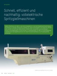
Image 1: Using this 3-axis portal in a<br />
system network, researchers at the<br />
Technical University of Munich are developing<br />
new concepts in simulationbased<br />
control development.<br />
1 Y-drive<br />
2 X-drive<br />
3 Gripper witch pneumatic Z-drive<br />
4 Photo cells<br />
of the automation functions, formal<br />
description and modeling methods<br />
from software development may be<br />
used, as well as task or sequence<br />
diagrams. Once the software functions<br />
have been designed, they are<br />
implemented in the development environment.<br />
State machines in state<br />
flow provide descriptions. These are<br />
able to represent both simple and<br />
complex drive functions.<br />
Connecting the developed control<br />
function to the system model makes<br />
it possible to perform model based<br />
testing. In addition to verifying the<br />
basic functions, it is also possible to<br />
test disturbance scenarios and identify<br />
potential adjustments to improve<br />
performance. the design, implementation<br />
and model-based testing<br />
stages should be repeated until they<br />
result in fully-functional and errorfree<br />
control code that can be implemented<br />
in the real system.<br />
the input variables for simulation<br />
module process control include the<br />
movement variables of the X and Y<br />
drives and the simulated sensor sig-<br />
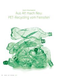
Image 2: Simulation<br />
model consisting of an<br />
open loop control model,<br />
system and closed-loop<br />
control models and signal<br />
evaluation in MATLAB ® /<br />
Simulink ® .<br />
nals. the system states encountered<br />
during movement are also represented<br />
in the process controller as<br />
states. the corresponding control<br />
values and transition conditions are<br />
also formulated in state flow syntax.<br />
process movements typically require<br />
more than binary control of<br />
Technology<br />
the drives. Often there are drives<br />
with speed or position control that<br />
are connected to one another via<br />
electronic cam profiles for coupled<br />
movements. the creation of these<br />
curves is an important part of the<br />
development of an automation<br />
solution. Image 3 shows a classic<br />
trapezoid movement profile with<br />
acceleration, speed and path. the<br />
development of the process characteristic<br />
curves takes place entirely<br />
in the simulation environment. this<br />
allows complex process movements<br />
and the corresponding control characteristic<br />
curves to be created and<br />
tested in the early phases of development.<br />
Via XmL exchange format<br />
(extended markup language) it is<br />
then possible to implement the process<br />
characteristic curves directly in<br />
B&R controllers without direct access<br />
to the target system.<br />
Step 3: Simulation and testing<br />
After the control functions have been<br />
tested, they are implemented. During<br />
the software test, the implemented<br />
functions are linked to the simulation<br />
model. the model then creates continuous<br />
processes, process movements<br />
and event-based processes in<br />
a common system. As a result, the<br />
overall behavior of the new system<br />
can be imitated realistically, and errors<br />
can be detected and corrected<br />
early and easily. the current testing<br />
environment is based on mAtLAB ®<br />
and integrates the following:<br />
■ process control model<br />
■ System behavior model<br />
■ process characteristic curves (control<br />
functions)<br />
■ Visualization of material flow<br />
An additional 3D environment was<br />
integrated for the gripper scenario,<br />
which displays the movements graphically<br />
for the developer. >><br />
<strong>automotion</strong> 07/2009<br />
17