2635 manual - BK Precision
2635 manual - BK Precision
2635 manual - BK Precision

Create successful ePaper yourself
Turn your PDF publications into a flip-book with our unique Google optimized e-Paper software.
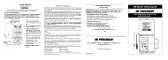
The fuseholder can be released by pressing its plastic retainers<br />
with the aid of a small screwdriver. The retainers are located on<br />
the right and left side of the holder and must be pressed towards<br />
the center. The fuse(s) can then be replaced and pressed in until<br />
locked on both sides.<br />
Use of patched fuses or short-circuiting of the fuseholder is not<br />
permissible; HAMEG assumes no liability whatsoever for any<br />
damage caused as a result, and all warranty claims become null<br />
and void.<br />
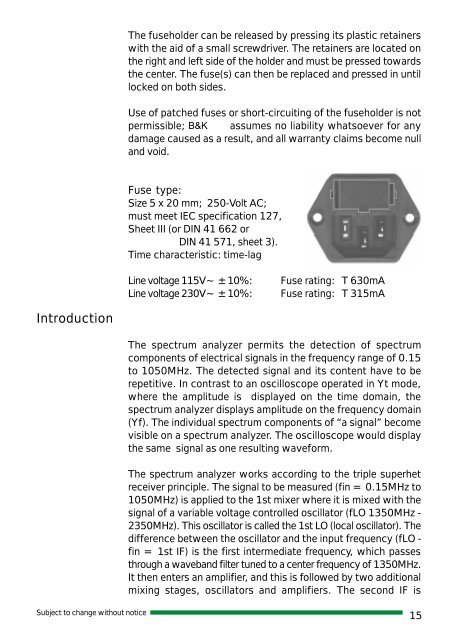
Fuse type:<br />
Size 5x20mm; 250-Volt AC;<br />
must meet IEC specification 127,<br />
Sheet III (or DIN 41 662 or<br />
DIN 41 571, sheet 3).<br />
Time characteristic: time-lag<br />
Introduction<br />
Line voltage 115V~ ±10%:<br />
Line voltage 230V~ ±10%:<br />
.<br />
Fuse rating: T 630mA<br />
Fuse rating: T 315mA<br />
The spectrum analyzer permits the detection of spectrum<br />
components of electrical signals in the frequency range of 0.15<br />
to 1050MHz. The detected signal and its content have to be<br />
repetitive. In contrast to an oscilloscope operated in Yt mode,<br />
where the amplitude is displayed on the time domain, the<br />
spectrum analyzer displays amplitude on the frequency domain<br />
(Yf). The individual spectrum components of “a signal” become<br />
visible on a spectrum analyzer. The oscilloscope would display<br />
the same signal as one resulting waveform.<br />
The spectrum analyzer works according to the triple superhet<br />
receiver principle. The signal to be measured (fin = 0.15MHz to<br />
1050MHz) is applied to the 1st mixer where it is mixed with the<br />
signal of a variable voltage controlled oscillator (fLO 1350MHz -<br />
2350MHz). This oscillator is called the 1st LO (local oscillator). The<br />
difference between the oscillator and the input frequency (fLO -<br />
fin = 1st IF) is the first intermediate frequency, which passes<br />
through a waveband filter tuned to a center frequency of 1350MHz.<br />
It then enters an amplifier, and this is followed by two additional<br />
mixing stages, oscillators and amplifiers. The second IF is<br />
Subject to change without notice<br />
15