2635 manual - BK Precision
2635 manual - BK Precision
2635 manual - BK Precision
You also want an ePaper? Increase the reach of your titles
YUMPU automatically turns print PDFs into web optimized ePapers that Google loves.
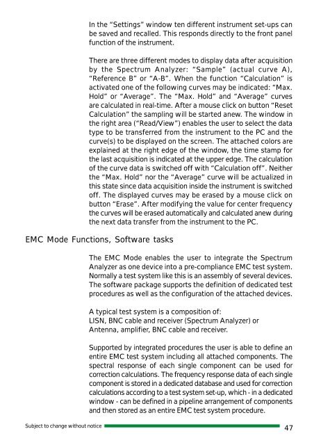
In the “Settings” window ten different instrument set-ups can<br />
be saved and recalled. This responds directly to the front panel<br />
function of the instrument.<br />
There are three different modes to display data after acquisition<br />
by the Spectrum Analyzer: “Sample” (actual curve A),<br />
“Reference B” or “A-B”. When the function “Calculation” is<br />
activated one of the following curves may be indicated: “Max.<br />
Hold” or “Average”. The “Max. Hold” and “Average” curves<br />
are calculated in real-time. After a mouse click on button “Reset<br />
Calculation” the sampling will be started anew. The window in<br />
the right area (“Read/View”) enables the user to select the data<br />
type to be transferred from the instrument to the PC and the<br />
curve(s) to be displayed on the screen. The attached colors are<br />
explained at the right edge of the window, the time stamp for<br />
the last acquisition is indicated at the upper edge. The calculation<br />
of the curve data is switched off with “Calculation off”. Neither<br />
the “Max. Hold” nor the “Average” curve will be actualized in<br />
this state since data acquisition inside the instrument is switched<br />
off. The displayed curves may be erased by a mouse click on<br />
button “Erase”. After modifying the value for center frequency<br />
the curves will be erased automatically and calculated anew during<br />
the next data transfer from the instrument to the PC.<br />
EMC Mode Functions, Software tasks<br />
The EMC Mode enables the user to integrate the Spectrum<br />
Analyzer as one device into a pre-compliance EMC test system.<br />
Normally a test system like this is an assembly of several devices.<br />
The software package supports the definition of dedicated test<br />
procedures as well as the configuration of the attached devices.<br />
A typical test system is a composition of:<br />
LISN, BNC cable and receiver (Spectrum Analyzer) or<br />
Antenna, amplifier, BNC cable and receiver.<br />
Supported by integrated procedures the user is able to define an<br />
entire EMC test system including all attached components. The<br />
spectral response of each single component can be used for<br />
correction calculations. The frequency response data of each single<br />
component is stored in a dedicated database and used for correction<br />
calculations according to a test system set-up, which - in a dedicated<br />
window - can be defined in a pipeline arrangement of components<br />
and then stored as an entire EMC test system procedure.<br />
Subject to change without notice<br />
47


