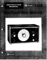
2635 manual - BK Precision
2635 manual - BK Precision
2635 manual - BK Precision

You also want an ePaper? Increase the reach of your titles
YUMPU automatically turns print PDFs into web optimized ePapers that Google loves.
Operating Instructions<br />
Attention!<br />
29.875MHz and the third is 2.75MHz. In the third IF stage, the<br />
signal can be selectively transferred through a filter with 400kHz<br />
or 20kHz bandwidth before arriving at an AM demodulator. The<br />
logarithmic output (video signal) is transferred directly, or via a low<br />
pass filter to another amplifier. This amplifier output is connected<br />
to the Y deflection plates of the CRT.<br />
The X deflection is performed with a ramp generator voltage. This<br />
voltage can also be superimposed on a dc voltage which allows<br />
for the control of 1st LO. The spectrum analyzer scans a frequency<br />
range depending on the ramp height. This span is determined by<br />
the scanwidth setting. In ZERO SCAN mode only the direct voltage<br />
controls the 1st LO.<br />
The HM5014 also includes a tracking generator. This generator<br />
provides sine wave voltages within the frequency range of 0.15<br />
to 1050MHz. The tracking generator frequency is determined by<br />
the first oscillator (1st LO) of the spectrum analyzer section.<br />
Spectrum analyzer and tracking generator are frequency<br />
synchronized.<br />
It is very important to read the paragraph “Safety” including the<br />
instructions prior to operating the HM5012/14. No special<br />
knowledge is necessary for the operation of the HM5012/14. The<br />
straightforward front panel layout and the limitation to basic<br />
functions guarantee efficient operation immediately. To ensure<br />
optimum operation of the instrument, some basic instructions<br />
need to be followed.<br />
The most sensitive component of the HM5012/HM5014 is<br />
the input section of the spectrum analyzer. It consists of<br />
the signal attenuator and the first mixer. Without input<br />
attenuation, the voltage at the input must not exceed<br />
+10dBm (0.7Vrms) AC or ±25 volt DC. With a maximum<br />
input attenuation of 40dB the AC voltage must not exceed<br />
+20dBm.<br />
These limits must not be exceeded<br />
otherwise the input attenuator and/or the first mixer would<br />
be destroyed.<br />
16 Subject to change without notice