Omron SX inverter manual
Omron SX inverter manual
Omron SX inverter manual

Create successful ePaper yourself
Turn your PDF publications into a flip-book with our unique Google optimized e-Paper software.
• The screening must be connected with a large<br />
contact surface of preferable 360 and always at<br />
both ends, to the motor housing and the VSD<br />
housing. When painted mounting plates are used,<br />
do not be afraid to scrape away the paint to obtain<br />
as large contact surface as possible at all mounting<br />
points for items such as saddles and the bare<br />
cable screening. Relying just on the connection<br />
made by the screw thread is not sufficient.<br />
NOTE: It is important that the motor housing has the<br />
same earth potential as the other parts of the machine.<br />
• The litz ground connection, see fig. 16, is only necessary<br />
if the mounting plate is painted. All the variable<br />
speed drives have an unpainted back side and<br />
are therefore suitable for mounting on an unpainted<br />
mounting plate.<br />
Connect the motor cables according to U - U, V - V<br />
and W - W.<br />
Pay special attention to the following points:<br />
• If paint must be removed, steps must be taken to<br />
prevent subsequent corrosion. Repaint after making<br />
connections!<br />
• The fastening of the whole variable speed drive<br />
housing must be electrically connected with the<br />
mounting plate over an area which is as large as<br />
possible. For this purpose the removal of paint is<br />
necessary. An alternative method is to connect the<br />
variable speed drive housing to the mounting plate<br />
with as short a length of litz wire as possible.<br />
• Try to avoid interruptions in the screening wherever<br />
possible.<br />
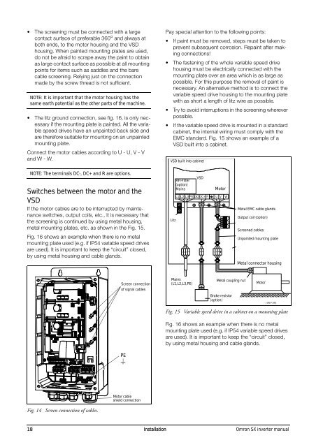
• If the variable speed drive is mounted in a standard<br />
cabinet, the internal wiring must comply with the<br />
EMC standard. Fig. 15 shows an example of a<br />
VSD built into a cabinet.<br />
VSD built into cabinet<br />
NOTE: The terminals DC-, DC+ and R are options.<br />
Switches between the motor and the<br />
VSD<br />
If the motor cables are to be interrupted by maintenance<br />
switches, output coils, etc., it is necessary that<br />
the screening is continued by using metal housing,<br />
metal mounting plates, etc. as shown in the Fig. 15.<br />
Fig. 16 shows an example when there is no metal<br />
mounting plate used (e.g. if IP54 variable speed drives<br />
are used). It is important to keep the “circuit” closed,<br />
by using metal housing and cable glands.<br />
Litz<br />
RFI-Filter<br />
(option)<br />
Mains<br />
VSD<br />
Motor<br />
Metal EMC cable glands<br />
Output coil (option)<br />
Screened cables<br />
Unpainted mounting plate<br />
Metal connector housing<br />
Screen connection<br />
of signal cables<br />
Mains<br />
(L1,L2,L3,PE)<br />
Metal coupling nut<br />
Motor<br />
Brake resistor<br />
(option)<br />
Fig. 15 Variable speed drive in a cabinet on a mounting plate<br />
Fig. 16 shows an example when there is no metal<br />
mounting plate used (e.g. if IP54 variable speed drives<br />
are used). It is important to keep the “circuit” closed,<br />
by using metal housing and cable glands.<br />
PE<br />
Motor cable<br />
shield connection<br />
Fig. 14 Screen connection of cables.<br />
18 Installation <strong>Omron</strong> <strong>SX</strong> <strong>inverter</strong> <strong>manual</strong>