Omron SX inverter manual
Omron SX inverter manual
Omron SX inverter manual

You also want an ePaper? Increase the reach of your titles
YUMPU automatically turns print PDFs into web optimized ePapers that Google loves.
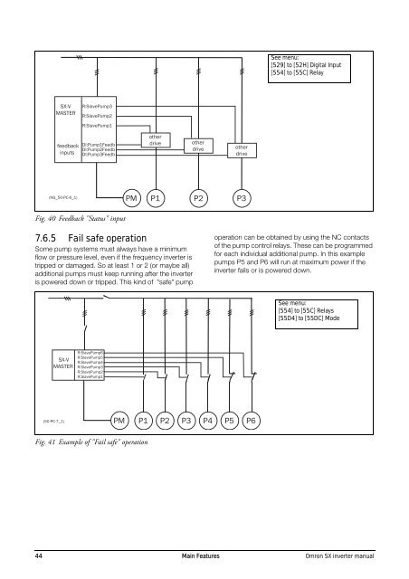
See menu:<br />
[529] to [52H] Digital Input<br />
[554] to [55C] Relay<br />
<strong>SX</strong>-V<br />
MASTER<br />
R:SlavePump3<br />
R:SlavePump2<br />
R:SlavePump1<br />
feedback<br />
inputs<br />
DI:Pump1Feedb<br />
DI:Pump2Feedb<br />
DI:Pump3Feedb<br />
other<br />
drive<br />
other<br />
drive<br />
other<br />
drive<br />
(NG_50-PC-6_1)<br />
Fig. 40 Feedback "Status" input<br />
PM<br />
P1 P2 P3<br />
7.6.5 Fail safe operation<br />
Some pump systems must always have a minimum<br />
flow or pressure level, even if the frequency <strong>inverter</strong> is<br />
tripped or damaged. So at least 1 or 2 (or maybe all)<br />
additional pumps must keep running after the <strong>inverter</strong><br />
is powered down or tripped. This kind of "safe" pump<br />
operation can be obtained by using the NC contacts<br />
of the pump control relays. These can be programmed<br />
for each individual additional pump. In this example<br />
pumps P5 and P6 will run at maximum power if the<br />
<strong>inverter</strong> fails or is powered down.<br />
See menu:<br />
[554] to [55C] Relays<br />
[55D4] to [55DC] Mode<br />
<strong>SX</strong>-V<br />
MASTER<br />
R:SlavePump6<br />
R:SlavePump5<br />
R:SlavePump4<br />
R:SlavePump3<br />
R:SlavePump2<br />
R:SlavePump1<br />
(50-PC-7_1)<br />
PM<br />
P1 P2 P3 P4 P5 P6<br />
Fig. 41 Example of "Fail safe" operation<br />
44 Main Features <strong>Omron</strong> <strong>SX</strong> <strong>inverter</strong> <strong>manual</strong>