Omron SX inverter manual
Omron SX inverter manual
Omron SX inverter manual

You also want an ePaper? Increase the reach of your titles
YUMPU automatically turns print PDFs into web optimized ePapers that Google loves.
Table 11<br />
L1,L2,L3<br />
PE<br />
U, V, W<br />
Mains and motor connection<br />
Mains supply, 3 -phase<br />
Safety earth<br />
Motor earth<br />
Motor output, 3-phase<br />
WARNING: In order to work safely the mains<br />
earth must be connected to PE and the motor<br />
earth to .<br />
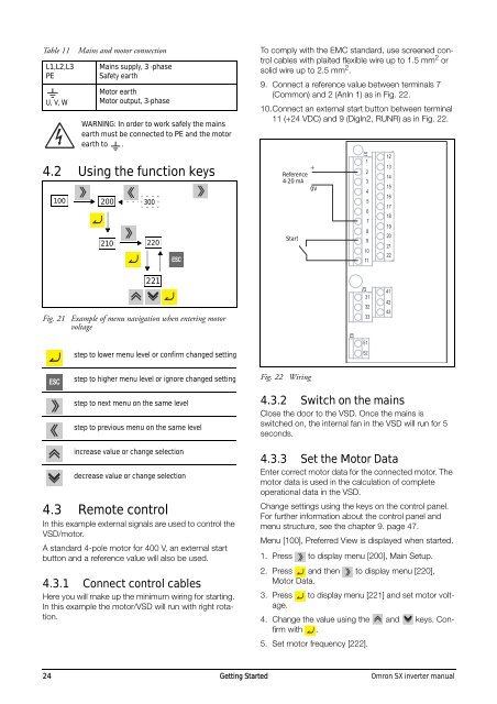
4.2 Using the function keys<br />
100 200 300<br />
210<br />
220<br />
To comply with the EMC standard, use screened control<br />
cables with plaited flexible wire up to 1.5 mm 2 or<br />
solid wire up to 2.5 mm 2 .<br />
9. Connect a reference value between terminals 7<br />
(Common) and 2 (AnIn 1) as in Fig. 22.<br />
10.Connect an external start button between terminal<br />
11 (+24 VDC) and 9 (DigIn2, RUNR) as in Fig. 22.<br />
Reference<br />
4-20 mA<br />
Start<br />
+<br />
0V<br />
X1<br />
1<br />
2<br />
3<br />
4<br />
5<br />
6<br />
7<br />
8<br />
9<br />
10<br />
11<br />
12<br />
13<br />
14<br />
15<br />
16<br />
17<br />
18<br />
19<br />
20<br />
21<br />
22<br />
221<br />
Fig. 21 Example of menu navigation when entering motor<br />
voltage<br />
step to lower menu level or confirm changed setting<br />
X3<br />
X2<br />
31<br />
32<br />
33<br />
51<br />
52<br />
41<br />
42<br />
43<br />
step to higher menu level or ignore changed setting<br />
step to next menu on the same level<br />
step to previous menu on the same level<br />
increase value or change selection<br />
decrease value or change selection<br />
4.3 Remote control<br />
In this example external signals are used to control the<br />
VSD/motor.<br />
A standard 4-pole motor for 400 V, an external start<br />
button and a reference value will also be used.<br />
4.3.1 Connect control cables<br />
Here you will make up the minimum wiring for starting.<br />
In this example the motor/VSD will run with right rotation.<br />
Fig. 22 Wiring<br />
4.3.2 Switch on the mains<br />
Close the door to the VSD. Once the mains is<br />
switched on, the internal fan in the VSD will run for 5<br />
seconds.<br />
4.3.3 Set the Motor Data<br />
Enter correct motor data for the connected motor. The<br />
motor data is used in the calculation of complete<br />
operational data in the VSD.<br />
Change settings using the keys on the control panel.<br />
For further information about the control panel and<br />
menu structure, see the chapter 9. page 47.<br />
Menu [100], Preferred View is displayed when started.<br />
1. Press to display menu [200], Main Setup.<br />
2. Press and then to display menu [220],<br />
Motor Data.<br />
3. Press to display menu [221] and set motor voltage.<br />
4. Change the value using the and keys. Confirm<br />
with .<br />
5. Set motor frequency [222].<br />
24 Getting Started <strong>Omron</strong> <strong>SX</strong> <strong>inverter</strong> <strong>manual</strong>