Omron SX inverter manual
Omron SX inverter manual
Omron SX inverter manual

Create successful ePaper yourself
Turn your PDF publications into a flip-book with our unique Google optimized e-Paper software.
5.5 Connecting the Control<br />
Signals<br />
5.5.1 Cables<br />
The standard control signal connections are suitable<br />
for stranded flexible wire up to 1.5 mm 2 and for solid<br />
wire up to 2.5 mm 2 .<br />
.<br />
5.5.2 Types of control signals<br />
Always make a distinction between the different types<br />
of signals. Because the different types of signals can<br />
adversely affect each other, use a separate cable for<br />
each type. This is often more practical because, for<br />
example, the cable from a pressure sensor may be<br />
connected directly to the variable speed drive.<br />
We can distinguish between the following types of<br />
control signals:<br />
Analogue inputs<br />
Voltage or current signals, (0-10 V, 0/4-20 mA) normally<br />
used as control signals for speed, torque and<br />
PID feedback signals.<br />
Analogue outputs<br />
Voltage or current signals, (0-10 V, 0/4-20 mA) which<br />
change slowly or only occasionally in value. In general,<br />
these are control or measurement signals.<br />
Digital<br />
Voltage or current signals (0-10 V, 0-24 V, 0/4-20 mA)<br />
which can have only two values (high or low) and only<br />
occasionally change in value.<br />
Data<br />
Usually voltage signals (0-5 V, 0-10 V) which change<br />
rapidly and at a high frequency, generally data signals<br />
such as RS232, RS485, Profibus, etc.<br />
Relay<br />
Relay contacts (0-250 VAC) can switch highly inductive<br />
loads (auxiliary relay, lamp, valve, brake, etc.).<br />
Signal<br />
type<br />
Maximum wire size Tightening<br />
torque<br />
Cable type<br />
Control signals<br />
0.5 Nm<br />
Analogue Rigid cable:<br />
Digital<br />
0.14-2.5 mm 2<br />
Flexible cable:<br />
Data 0.14-1.5 mm 2<br />
Relay 0.25-1.5 mm 2<br />
Cable with ferrule:<br />
Screened<br />
Screened<br />
Screened<br />
Not screened<br />
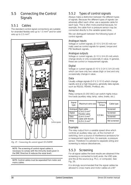
Fig. 25 Connecting the control signals <strong>SX</strong>-D4090<br />
NOTE: The screening of control signal cables is<br />
necessary to comply with the immunity levels given in<br />
the EMC Directive (it reduces the noise level).<br />
NOTE: Control cables must be separated from motor and<br />
mains cables.<br />
Example:<br />
The relay output from a variable speed drive which<br />
controls an auxiliary relay can, at the moment of<br />
switching, form a source of interference (emission) for<br />
a measurement signal from, for example, a pressure<br />
sensor. Therefore it is advised to separate wiring and<br />
screening to reduce disturbances.<br />
5.5.3 Screening<br />
For all signal cables the best results are obtained if the<br />
screening is connected to both ends: the VSD side<br />
and the at the source (e.g. PLC, or computer). See<br />
Fig. 26.<br />
It is strongly recommended that the signal cables be<br />
allowed to cross mains and motor cables at a 90<br />
30 Control Connections <strong>Omron</strong> <strong>SX</strong> <strong>inverter</strong> <strong>manual</strong>