Omron SX inverter manual
Omron SX inverter manual
Omron SX inverter manual

Create successful ePaper yourself
Turn your PDF publications into a flip-book with our unique Google optimized e-Paper software.
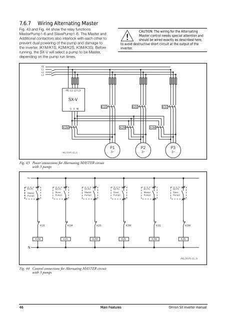
7.6.7 Wiring Alternating Master<br />
Fig. 43 and Fig. 44 show the relay functions<br />
MasterPump1-6 and SlavePump1-6. The Master and<br />
Additional contactors also interlock with each other to<br />
prevent dual powering of the pump and damage to<br />
the <strong>inverter</strong>. (K1M/K1S, K2M/K2S, K3M/K3S). Before<br />
running, the <strong>SX</strong>-V will select a pump to be Master,<br />
depending on the pump run times.<br />
CAUTION: The wiring for the Alternating<br />
Master control needs special attention and<br />
! should be wired exactly as described here,<br />
to avoid destructive short circuit at the output of the<br />
<strong>inverter</strong>.<br />
PE<br />
L1<br />
L2<br />
L3<br />
PE L1 L2 L3<br />
<strong>SX</strong>-V<br />
U V W<br />
K1S<br />
K2S<br />
K3S<br />
K1M<br />
K2M<br />
K3M<br />
(NG_50-PC-10_1)<br />
P1<br />
3~<br />
P2<br />
3~<br />
P3<br />
3~<br />
Fig. 43 Power connections for Alternating MASTER circuit<br />
with 3 pumps<br />
~<br />
B1:R1<br />
Master<br />
Pump1<br />
B2:R1<br />
Slave<br />
Pump1<br />
B1:R2<br />
Master<br />
Pump2<br />
B2:R2<br />
Slave<br />
Pump2<br />
B1:R3<br />
Master<br />
Pump3<br />
B2:R3<br />
Slave<br />
Pump3<br />
K1S K1M K2S<br />
K2M<br />
K3S<br />
K3M<br />
K1M<br />
K1S<br />
K2M<br />
K2S<br />
K3M<br />
K3S<br />
N<br />
(NG_50-PC-11_3)<br />
Fig. 44 Control connections for Alternating MASTER circuit<br />
with 3 pumps<br />
46 Main Features <strong>Omron</strong> <strong>SX</strong> <strong>inverter</strong> <strong>manual</strong>