Omron SX inverter manual
Omron SX inverter manual
Omron SX inverter manual

You also want an ePaper? Increase the reach of your titles
YUMPU automatically turns print PDFs into web optimized ePapers that Google loves.
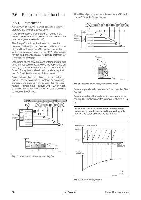
7.6 Pump sequencer function<br />
7.6.1 Introduction<br />
A maximum of 4 pumps can be controlled with the<br />
standard <strong>SX</strong>-V variable speed drive.<br />
If I/O Board options are installed, a maximum of 7<br />
pumps can be controlled. The I/O Board can also be<br />
used as a general extended I/O.<br />
The Pump Control function is used to control a<br />
number of drives (pumps, fans, etc., with a maximum<br />
of 3 additional drives per I/O-board connected) of<br />
which one is always driven by the <strong>SX</strong>-V. Other names<br />
for this kind of controllers are 'Cascade controller' or<br />
'Hydrophore controller'.<br />
Depending on the flow, pressure or temperature, additional<br />
pumps can be activated via the appropriate signals<br />
by the output relays of the <strong>SX</strong>-V and/or the I/O<br />
Board. The system is developed in such a way that<br />
one <strong>SX</strong>-V will be the master of the system.<br />
Select relay on the control board or on an option<br />
board. The relays are set to functions for controlling<br />
pumps. In the pictures in this section, the relays are<br />
named R:Function, e.g. R:SlavePump1, which means<br />
a relay on the control board or on an option board set<br />
to function SlavePump1.<br />
Set FLOW<br />
Feedback<br />
FLOW<br />
<strong>SX</strong>-V<br />
R:SlavePump1<br />
MASTER<br />
R:SlavePump2<br />
AnIn<br />
PI D<br />
AnIn<br />
PM<br />
R:SlavePump3<br />
R:SlavePump4<br />
P1 P2 P3 P4 P5 P6<br />
All additional pumps can be activated via a VSD, soft<br />
starter, Y/ or D.O.L. switches.<br />
Set<br />
PRESSURE<br />
Feedback<br />
PRESSURE<br />
<strong>SX</strong>-V<br />
R:SlavePump1<br />
MASTER<br />
R:SlavePump2<br />
AnIn<br />
PI D<br />
AnIn<br />
PM<br />
R:SlavePump3<br />
R:SlavePump4<br />
R:SlavePump5<br />
R:SlavePump6<br />
Pr essur e<br />
4<br />
3<br />
2<br />
1<br />
P1 P2 P3 P4 P5 P6<br />
Power<br />
Flow<br />
Fig. 36 Pressure control with pump control option<br />
(50-PC-2_1)<br />
Pumps in parallel will operate as a flow controller, See<br />
Fig. 35.<br />
Pumps in series will operate as a pressure controller<br />
see Fig. 36. The basic control principle is shown in Fig.<br />
37.<br />
NOTE: Read this instruction <strong>manual</strong> carefully before<br />
commencing installation, connecting or working with<br />
the variable speed drive with Pump Control.<br />
R:SlavePump5<br />
R:SlavePump6<br />
FREQUENCY (master pump P)<br />
Add pump<br />
Pr essur e<br />
Stop pump<br />
Power<br />
Flow<br />
1 2 3 4<br />
Fig. 35 Flow control with pump control option<br />
(50-PC-1_1)<br />
P=on<br />
FLOW /<br />
PRESSURE<br />
P1=on P2=on P3=on P4=on P5=on P6=on<br />
FLOW /<br />
PRESSURE<br />
TIM E<br />
(50-PC-3_1)<br />
Fig. 37 Basic Control principle<br />
42 Main Features <strong>Omron</strong> <strong>SX</strong> <strong>inverter</strong> <strong>manual</strong>