pdf download - Software and Computer Technology - TU Delft
pdf download - Software and Computer Technology - TU Delft
pdf download - Software and Computer Technology - TU Delft

Create successful ePaper yourself
Turn your PDF publications into a flip-book with our unique Google optimized e-Paper software.
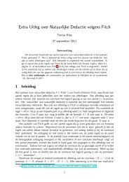
B.2 System Data Case Study Details<br />
Name<br />
Imin<br />
Imax<br />
Iact<br />
Iset<br />
Vact<br />
Vset<br />
Pset<br />
Pact<br />
State<br />
Note<br />
Error(s) found<br />
Description<br />
minimum motor current towards the hardware in milliampere<br />
maximum motor current towards the hardware in milliampere.<br />
actual motor current from the hardware in milliampere<br />
actual set motor current from the hardware in milliampere<br />
actual speed from the hardware derived by emk sensing of the motor in 0.1°/s or<br />
0.1mm/s<br />
set speed towards the hardware in 0.1°/s or 0.1mm/s.<br />
actual position from hardware in 0.1°or 0.1mm.<br />
the set position of the motion controller in 0.1°or 0.1mm.<br />
the movement state of the motion controller.<br />
indicates whether the units are 0.1°or mm.<br />
This is a readable representation of the error status register.<br />
Table B.1: The meaning of the system data that can be found in an error 11 entry.<br />
a LUC the pair is made specific for a certain task. Each pair forms the control unit of some<br />
movements. The MVR is part of the actuator path <strong>and</strong> is used to amplify the electronic signal<br />
from the processing boards to the motor <strong>and</strong> brake.<br />
SPR: The unit that contains the motor, brake, potentiometer <strong>and</strong> encoder. The former two are the<br />
actuators of the movement. The latter two are used as sensors <strong>and</strong> constitute the start of the<br />
sensor feedback path of the control loop.<br />
Frontal St<strong>and</strong>: The mechanical body that has the collimator <strong>and</strong> flat detector on its far ends. It can<br />
be positioned relative to the patient in order to transmit X-ray through the patient.<br />
B.2 System Data<br />
Table B.1 shows the meaning of the system data that Philips Cardio-Vascular X-Ray Systems produce<br />
in case error 11 occurred.<br />
B.3 Behavior<br />
Below follows a description of the behavior of the system in natural language. A formal specification<br />
is the corresponding Lydia code that is listed in appendix C. The desired behavior is realized<br />
by three nested control loops. The writing below follows the convention to use this font for all<br />
referenced names of signals <strong>and</strong> FRUs (also shown in Figure 5.3). The first control loop controls<br />
the position. The setpoint for the position (Pset) is determined by integrating the requested speed<br />
(V_user). The (nominal) error (e_pos) is calculated by subtracting the actual position (Pact). This<br />
error is used by position controller CTR_pos to calculate a setpoint for the speed (Vset) in such a<br />
way that that the st<strong>and</strong> passes position Pset at the requested speed. Therefore, Vset depends on<br />
e_pos, V_user <strong>and</strong> Vfw. The latter is a feed forward variable that is determined during calibration.<br />
The next control loop controls the speed. Figure B.2 shows the dynamics that should be thought of<br />
when controlling the speed. It can be divided in a left <strong>and</strong> right part, both parts representing a lever.<br />
86