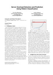
pdf download - Software and Computer Technology - TU Delft
pdf download - Software and Computer Technology - TU Delft
pdf download - Software and Computer Technology - TU Delft

Create successful ePaper yourself
Turn your PDF publications into a flip-book with our unique Google optimized e-Paper software.
5.5 MBD Implementation 2<br />
Diagnosing the Beam Propeller Movement<br />
of the Frontal St<strong>and</strong><br />
5.4.5 Results of the MBD-1 Implementation<br />
The goal of this step was to define a MBD implementation to fault diagnosis that achieves the same<br />
entropy as experts are able to achieve. The LUT, that specifies the outcome of the LYDIA diagnostic<br />
engine for all possible observations, is exactly equal to Table 5.5. Consequently, the entropy (H) of<br />
the MBD implementation (MBD-1) is the same:<br />
H MBD−1 = 0.9453 (5.4)<br />
5.5 MBD Implementation 2<br />
This sections presents a second iteration of steps 2, 3, <strong>and</strong> 4 of the case study approach. The<br />
intended result is that the uncertainty decreases without having to make additional measurements,<br />
but by improving the model. The idea is as follows. A good diagnostic approach takes advantage<br />
of every possible inference that could be drawn out of all available system data. Therefore, in this<br />
iteration, experts <strong>and</strong> modeler search for more symptoms within the examined system data.<br />
If one tries to ’discover’ more symptoms in the same system data, it is useful to discretize the<br />
system data. Most data of the fault scenarios shown in Table 5.4 is in the domain of integers. Humans<br />
experience difficulties to reason about faulty components using such a level of detail. As<br />
explained in the previous chapter, humans are better able to perform fault diagnosis using a domain<br />
with few members. The applied discretization is defined by source domain N <strong>and</strong> target domain M.<br />
The target domain M is defined as follows:<br />
⎧<br />
T L,<br />
⎪⎨<br />
M =<br />
⎪⎩<br />
: Too Low. The threshold has been violated.<br />
L, : Low. Negative polarity of the value.<br />
N, : Nominal. Close to zero.<br />
H, : High. Positive polarity of the value.<br />
T H : Too High. The threshold has been violated.<br />
The source domain is the domain of natural numbers N. The target domain values can be chosen<br />
in many ways. In this case these particular values (L denotes negative polarity, N denotes close<br />
to zero, etc.) are meaningful when reasoning from first principles about the target system. The<br />
mapping of values in the source domain N to the target domain M is shown in Appendix B.5. Table<br />
5.6 shows the discretized values of the observations. Note that the table shows other variables than<br />
shown in Table 5.4. Discretizing the variables Pact <strong>and</strong> Pset is not useful, because the system does<br />
not show different behavior for different angles of the frontal st<strong>and</strong>. The variables Imin <strong>and</strong> Imax<br />
are used to calculate the polarity of Iset <strong>and</strong> Iact (see Appendix B.5), <strong>and</strong> do not have value on<br />
their own.<br />
The values of Table 5.6 are much easier to interpret than the raw system data of Table 5.4.<br />
Much of the discretized variables have values that experts expect (see Section 5.3). A current error<br />
implies that the Iact <strong>and</strong> Iset differ. A speed error implies that Vact <strong>and</strong> Vset differ. From system<br />
behavior, it is also expected that the value of Iset has the same polarity as the value of e_sp. This<br />
does not hold for fault scenario 3, as can be seen in Table 5.6. In this fault scenario, the inequality<br />
of Iset <strong>and</strong> e_sp is a symptom of a malfunctioning system. Figure 5.3 shows that CTR_speed must<br />
be at false. This unit is of lower than the chosen granularity, <strong>and</strong> therefore the symptom identifies<br />
that the LUC_Extension is malfunctioning.<br />
62