Crisman Annual Report 2009 - Harold Vance Department of ...
Crisman Annual Report 2009 - Harold Vance Department of ...
Crisman Annual Report 2009 - Harold Vance Department of ...

You also want an ePaper? Increase the reach of your titles
YUMPU automatically turns print PDFs into web optimized ePapers that Google loves.
CO 2<br />
Mobility Control using Cross-Linked Gel and CO 2<br />
Viscosifiers<br />
Objectives<br />
1. Investigate and test different approaches in the<br />
laboratory to control CO 2<br />
mobility during CO 2<br />
flooding to increase the overall efficiency.<br />
2. Develop a simulation model which would<br />
incorporate the CO 2<br />
viscosity relationship<br />
with pressure, then use this model to predict<br />
viscosified CO 2<br />
flooding efficiency in comparison<br />
with pure CO 2<br />
flooding.<br />
Accomplishments<br />
The visualization <strong>of</strong> CO 2<br />
flow within core using CT-<br />
Scanning provides us with a more direct observation<br />
for the CO 2<br />
flood fronts in the core. We have studied<br />
two approaches to control CO 2<br />
mobility: HPAM/<br />
Cr(III) gel conformance control treatment, and the<br />
direct increase <strong>of</strong> CO 2<br />
viscosity using viscosifier<br />
chemicals (PVAc or Polysiloxanes).<br />
For the study <strong>of</strong> gel conformance control, crosslinked<br />
HPAM/Cr(III) gel was applied to fractured cores<br />
in order to get incremental oil recovery. We have<br />
tested 10,000 ppm <strong>of</strong> high concentration gel and<br />
found out it had a better stability when compared<br />
with the 3,000 ppm gel we used previously. The<br />
10,000 ppm gel appeared to be more stable and<br />
also gave a higher pressure drop in CO 2<br />
flooding,<br />
which means better mobility control.<br />
For the study <strong>of</strong> CO 2<br />
viscosifiers, a controlled CO 2<br />
flooding experiment using pure CO 2<br />
was conducted<br />
and the expected low recovery was obtained due to<br />
rapid breakthrough <strong>of</strong> CO 2<br />
through the fracture. The<br />
first low molecular weight viscosifier was studied<br />
and we observed significant differences in CO 2<br />
flood<br />
front images. A more uniform, piston-like CO 2<br />
flood<br />
front was formed in the viscosifier case, suggesting<br />
a reduction in CO 2<br />
viscosity. Higher oil recovery was<br />
also observed using viscosified CO 2<br />
.<br />
A black-oil pseudo-miscible model for an oil field in<br />
Peru was developed using data from one <strong>of</strong> the wells.<br />
To account for the increase in CO 2<br />
viscosity, new<br />
viscosity/pressure relationships were integrated into<br />
the simulation model. We are currently simulating<br />
viscosified cases to develop cost benefit relations.<br />
Future Work<br />
More viscosifier chemical structures will be studied<br />
to compare the efficiency differences between low<br />
78<br />
and high molecular weight viscosifiers. The injection<br />
scheme will be altered to reflect field sequence <strong>of</strong><br />
events: we will begin with pure CO 2<br />
until no more<br />
oil is recovered, and then we will begin injecting<br />
viscosified CO 2<br />
to determine the incremental<br />
recovery caused by viscosified CO 2<br />
after pure CO 2<br />
injection. We will also develop simulation tools<br />
capable <strong>of</strong> accounting for viscosified CO 2<br />
cases.<br />
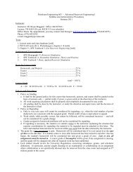
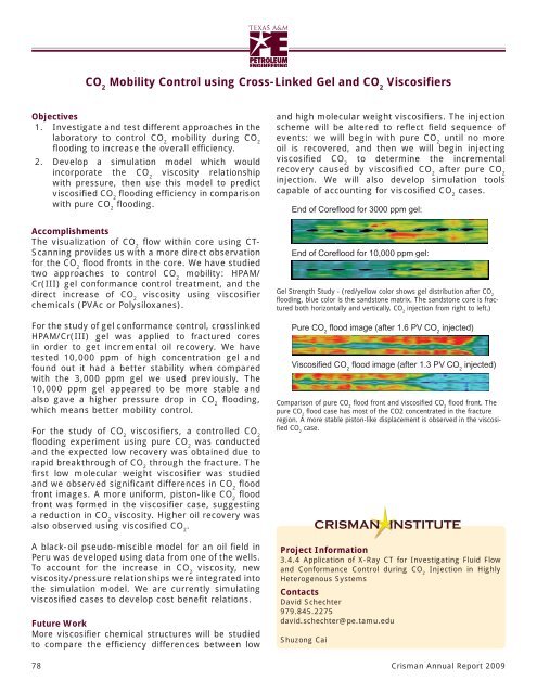
End <strong>of</strong> Coreflood for 3000 ppm gel:<br />
End <strong>of</strong> Coreflood for 10,000 ppm gel:<br />
Gel Strength Study - (red/yellow color shows gel distribution after CO 2<br />
flooding, blue color is the sandstone matrix. The sandstone core is fractured<br />
both horizontally and vertically. CO 2<br />
injection from right to left.)<br />
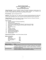
Pure CO 2<br />
flood image (after 1.6 PV CO 2<br />
injected)<br />
Viscosified CO 2<br />
flood image (after 1.3 PV CO 2<br />
injected)<br />
Comparison <strong>of</strong> pure CO 2<br />
flood front and viscosified CO 2<br />
flood front. The<br />
pure CO 2<br />
flood case has most <strong>of</strong> the CO2 concentrated in the fracture<br />
region. A more stable piston-like displacement is observed in the viscosified<br />
CO 2<br />
case.<br />
Project Information<br />
3.4.4 Application <strong>of</strong> X-Ray CT for Investigating Fluid Flow<br />
and Conformance Control during CO 2<br />
Injection in Highly<br />
Heterogenous Systems<br />
Contacts<br />
David Schechter<br />
979.845.2275<br />
david.schechter@pe.tamu.edu<br />
Shuzong Cai<br />
CRISMAN INSTITUTE<br />
<strong>Crisman</strong> <strong>Annual</strong> <strong>Report</strong> <strong>2009</strong>