FIRE-RESISTANCE RATINGS WITH STEEL JOISTS Hundreds of fire tests on steel joist-supported assemblies have been conducted at nationally recognized testing laboratories in accordance with ASTM Standard E119, ANSI A2.1/UL 263, and NFPA 251. Because of practical loading restrictions and limitations of furnace dimensions, the vast majority of these tests were run using lightweight joists – normally from 8 inches to 14 inches deep. This practice was advantageous in that it established the minimum acceptable joists at the shallow and lightweight end of the joist load tables. The specified minimum size joist as listed in Underwriters Laboratories (U.L.) Fire Resistance Designs is the joist which combines the required minimum depth and minimum weight per foot. <strong>Joist</strong>s, of the same series, which meet, or exceed the specified minimums may be used provided the accessories are compatible. The dimension from the bottom chord of joists to the ceiling, whether given or calculated, is a minimum. K-Series <strong>Joist</strong>s, LH Series <strong>Joist</strong>s and <strong>Joist</strong> Girders specified in floor- or roof-ceiling assemblies, shall be designed and manufactured in accordance with the Steel <strong>Joist</strong> Institute’s Specifications adopted November 4, 1985, revised to May 1, 2000. Many of U.L.’s Fire Rated Assemblies now specifically list K-Series <strong>Joist</strong>s. When a K-Series <strong>Joist</strong> is specified in a particular U.L. assembly the K-Series <strong>Joist</strong> shall have its design stress limited only if the assembly specifically limits the design stress of the K-Series <strong>Joist</strong>. K-Series <strong>Joist</strong>s may be substituted for S-, J-, and/or H- Series <strong>Joist</strong>s specified in U.L. floor-, or roof-ceiling designs as follows: Floor-Ceiling Assemblies: K-Series Steel <strong>Joist</strong>s of equal or greater depth weight per foot may be substituted for any S-, J-, and/or H-Series <strong>Joist</strong> in any floor-ceiling design which employs a structural concrete floor and suspended membrane ceiling. Roof-Ceiling Assemblies: K-Series Steel <strong>Joist</strong>s of equal or greater depth and weight per foot may be substituted for any S-, J-, and/or H-Series <strong>Joist</strong>s in any roof-ceiling design with the following restrictions: a) Minimum Nominal Depth = 10 inches (254mm) b) Maximum Tensile Stress = 26 KSI (179 MPa) Any stress limitation specified in a U.L. floor or roof fire rated assembly containing S, J and/or H Series <strong>Joist</strong>s shall remain applicable when a K-Series <strong>Joist</strong> is substituted. Also, certain U.L. assembly designs contain restrictions regarding minimum allowable joist member sizes, areas of steel, and/or bridging material sizes. These restrictions remain applicable when a K-Series <strong>Joist</strong> is substituted and it is the responsibility of the specifying professional to list all such restrictions on the contract drawings. The following procedure may be used to substitute the proper K-Series <strong>Joist</strong> for any S-, J-, and/or H-Series <strong>Joist</strong> listed in a U.L. design assembly. 1. Determine the uniform load per foot the joist is required to support. 2. Select a design from the U.L. “Fire Resistance Directory” that matches the building construction and has the required fire rating. 3. a) Floor Assemblies: x x x x x x x x x x x x x x x x Adjust the design load per foot calculated in step #1 for any required reduction in stress level by multiplying the load by a factor of 30 ksi (207MPa) divided by the specified stress level, i.e. [30/24 (207/165), 30/22 (207/152) etc.]. b) Roof Assemblies: x x x x x x x x x x x x x x x x Adjust the design load per foot calculated in step #1 by multiplying by the factor of 30/26 (207/179), or a greater factor if the particular assembly design requires a lessor stress level. 4. Enter the K-Series Economy Table and select the proper joist for the calculated load requirement. 5. Insure that the K-Series <strong>Joist</strong> selected has a depth and load table weight per foot equal to, or greater than, the S-, J- and/or H-Series joist listed in the U.L. Design. <strong>Joist</strong>s used in roof assemblies must have a minimum depth of 10 inches (254mm). So that the proper K-Series <strong>Joist</strong> can be selected for U.L. Designs not presently containing a K-Series designation the weights of various S-, J-, and H-Series <strong>Joist</strong>s used in the U.L. Fire Resistance Designs are listed below: 103
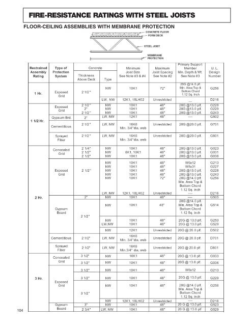
FIRE-RESISTANCE RATINGS WITH STEEL JOISTS FLOOR-CEILING ASSEMBLIES WITH MEMBRANE PROTECTION 104
- Page 2 and 3:
TABLE OF CONTENTS **IMPORTANT NOTIC
- Page 4 and 5:
VULCRAFT OF NEW YORK, INC. LOCATION
- Page 6 and 7:
JOIST DESIGN COMMENTARY FLOOR VIBRA
- Page 8 and 9:
LOAD AND RESISTANCE FACTOR DESIGN T
- Page 10 and 11:
VULCRAFT K SERIES / GENERAL INFORMA
- Page 12 and 13:
STANDARD LOAD TABLE/OPEN WEB STEEL
- Page 14 and 15:
STANDARD LOAD TABLE/OPEN WEB STEEL
- Page 16 and 17:
KCS JOISTS EXAMPLE 2 OPTION A: Use
- Page 18 and 19:
KCS JOISTS LOAD TABLE (SYSTEME INTE
- Page 20 and 21:
STANDARD LOAD TABLE IN METRIC UNITS
- Page 22 and 23:
STANDARD LOAD TABLE IN METRIC UNITS
- Page 24 and 25:
OPEN WEB STEEL JOISTS, K-SERIES In
- Page 26 and 27:
OPEN WEB STEEL JOISTS, K-SERIES 4.5
- Page 28 and 29:
OPEN WEB STEEL JOISTS, K-SERIES NUM
- Page 30 and 31:
OPEN WEB STEEL JOISTS, K-SERIES 5.9
- Page 32 and 33:
ACCESSORIES AND DETAILS 2.5K SERIES
- Page 34 and 35:
ACCESSORIES AND DETAILS K SERIES OP
- Page 36 and 37:
ACCESSORIES AND DETAILS BRIDGING RE
- Page 38 and 39:
OPEN WEB STEEL JOISTS, K-SERIES TOP
- Page 40 and 41:
OPEN WEB STEEL JOISTS, K-SERIES TOP
- Page 42 and 43:
ACCESSORIES AND DETAILS LH & DLH SE
- Page 44 and 45:
VULCRAFT LH & DLH SERIES / GENERAL
- Page 46 and 47:
STANDARD LOAD TABLE/LONG SPAN STEEL
- Page 48 and 49:
STANDARD LOAD TABLE DEEP LONGSPAN S
- Page 50 and 51:
METRIC LOAD TABLE LONGSPAN STEEL JO
- Page 52 and 53:
STANDARD LOAD TABLE IN METRIC UNITS
- Page 54 and 55: STANDARD LOAD TABLE IN METRIC UNITS
- Page 56 and 57: LONGSPAN AND DEEP LONGSPAN STEEL JO
- Page 58 and 59: LONGSPAN AND DEEP LONGSPAN STEEL JO
- Page 60 and 61: LONGSPAN AND DEEP LONGSPAN STEEL JO
- Page 62 and 63: LONGSPAN AND DEEP LONGSPAN STEEL JO
- Page 64 and 65: VULCRAFT SLH / GENERAL INFORMATION
- Page 66 and 67: ACCESSORIES AND DETAILS SLH SERIES
- Page 68 and 69: VULCRAFT LOAD TABLE SUPER LONGSPAN
- Page 70 and 71: SPECIFICATIONS FOR VULCRAFT SUPER L
- Page 72 and 73: SPECIFICATIONS FOR VULCRAFT SUPER L
- Page 74 and 75: SPECIFICATIONS FOR VULCRAFT SUPER L
- Page 76 and 77: VULCRAFT JOIST GIRDERS WHAT ARE JOI
- Page 78 and 79: JOIST GIRDER NOTES If fixed end mom
- Page 80 and 81: MOMENT CONNECTION DETAILS Presented
- Page 82 and 83: DESIGN GUIDE WEIGHT TABLE FOR JOIST
- Page 84 and 85: DESIGN GUIDE WEIGHT TABLE FOR JOIST
- Page 86 and 87: DESIGN GUIDE WEIGHT TABLE FOR JOIST
- Page 88 and 89: DESIGN GUIDE WEIGHT TABLE FOR JOIST
- Page 90 and 91: Based on an allowable tensile stres
- Page 92 and 93: JOIST GIRDERS DESIGN GUIDE WEIGHT T
- Page 94 and 95: JOIST GIRDERS DESIGN GUIDE WEIGHT T
- Page 96 and 97: JOIST GIRDERS DESIGN GUIDE WEIGHT T
- Page 98 and 99: STANDARD SPECIFICATIONS FOR JOIST G
- Page 100 and 101: JOIST GIRDERS For cold-formed secti
- Page 102 and 103: JOIST GIRDERS The designed detail o
- Page 106 and 107: FIRE-RESISTANCE RATINGS WITH STEEL
- Page 108 and 109: ECONOMICAL JOIST GUIDE Combined K,
- Page 110 and 111: ECONOMICAL JOIST GUIDE Combined K,
- Page 112 and 113: ECONOMICAL JOIST GUIDE Combined K,
- Page 114 and 115: ECONOMICAL JOIST GUIDE Combined K,
- Page 116 and 117: ECONOMICAL JOIST GUIDE Combined K,
- Page 118 and 119: ECONOMICAL JOIST GUIDE Combined K,
- Page 120 and 121: RECOMMENDED CODE OF STANDARD PRACTI
- Page 122 and 123: RECOMMENDED CODE OF STANDARD PRACTI
- Page 124 and 125: RECOMMENDED CODE OF STANDARD PRACTI
- Page 126 and 127: RECOMMENDED CODE OF STANDARD PRACTI
- Page 128 and 129: PUBLICATIONS Vulcraft (Refer to bac