Vulcraft_Joist_Catal..
Vulcraft_Joist_Catal..
Vulcraft_Joist_Catal..
- No tags were found...
You also want an ePaper? Increase the reach of your titles
YUMPU automatically turns print PDFs into web optimized ePapers that Google loves.
LONGSPAN AND DEEP LONGSPAN STEEL JOISTS, LH- AND DLH-SERIES<br />
(b) Steel<br />
Ends of LH and DLH-Series <strong>Joist</strong>s resting on steel<br />
supports shall be attached thereto with a minimum of<br />
two ¹⁄₄ inch (6mm) fillet welds 2 inches (51mm) or with<br />
two ³⁄₄ inch (19mm) bolts or the equivalent. In steel<br />
frames, where columns are not framed in at least two<br />
directions with structural steel members, bearing seats<br />
for joists at column lines shall be fabricated to allow for<br />
field bolting.<br />
(c) Uplift<br />
Where uplift forces are a design consideration, roof<br />
joists shall be anchored to resist such forces.<br />
104.8 JOIST SPACING<br />
<strong>Joist</strong>s shall be spaced so that the loading on each joist does<br />
not exceed the allowable load given for the particular designation<br />
and clear span in the Load Table.<br />
104.9 FLOOR AND ROOF DECKS<br />
(a) Material<br />
Floor and roof decks may consist of cast-in-place or<br />
pre-cast concrete or gypsum, formed steel, wood, or<br />
other suitable material capable of supporting the<br />
required load at the specified joist spacing.<br />
(b) Thickness<br />
Cast-in-place slabs shall be not less than 2 inches (51<br />
mm) thick.<br />
(c) Centering<br />
Centering for structural slabs may be ribbed metal lath,<br />
corrugated steel sheets, paper-backed welded wire fabric,<br />
removable centering or any other suitable material<br />
capable of supporting the slab at the designated joist<br />
spacing. Centering shall not cause lateral displacement<br />
or damage to the top chord of joists during installation or<br />
removal of the centering or placing of the concrete.<br />
(d) Bearing<br />
Slabs or decks shall bear uniformly along the top chords<br />
of the joists.<br />
(e) Attachments<br />
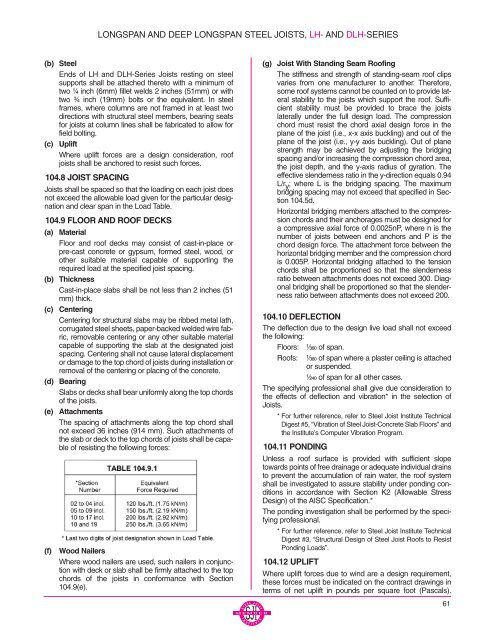
The spacing of attachments along the top chord shall<br />
not exceed 36 inches (914 mm). Such attachments of<br />
the slab or deck to the top chords of joists shall be capable<br />
of resisting the following forces:<br />
(f)<br />
Wood Nailers<br />
Where wood nailers are used, such nailers in conjunction<br />
with deck or slab shall be firmly attached to the top<br />
chords of the joists in conformance with Section<br />
104.9(e).<br />
(g) <strong>Joist</strong> With Standing Seam Roofing<br />
The stiffness and strength of standing-seam roof clips<br />
varies from one manufacturer to another. Therefore,<br />
some roof systems cannot be counted on to provide lateral<br />
stability to the joists which support the roof. Sufficient<br />
stability must be provided to brace the joists<br />
laterally under the full design load. The compression<br />
chord must resist the chord axial design force in the<br />
plane of the joist (i.e., x-x axis buckling) and out of the<br />
plane of the joist (i.e., y-y axis buckling). Out of plane<br />
strength may be achieved by adjusting the bridging<br />
spacing and/or increasing the compression chord area,<br />
the joist depth, and the y-axis radius of gyration. The<br />
effective slenderness ratio in the y-direction equals 0.94<br />
L/r y ; where L is the bridging spacing. The maximum<br />
bridging spacing may not exceed that specified in Section<br />
104.5d.<br />
Horizontal bridging members attached to the compression<br />
chords and their anchorages must be designed for<br />
a compressive axial force of 0.0025nP, where n is the<br />
number of joists between end anchors and P is the<br />
chord design force. The attachment force between the<br />
horizontal bridging member and the compression chord<br />
is 0.005P. Horizontal bridging attached to the tension<br />
chords shall be proportioned so that the slenderness<br />
ratio between attachments does not exceed 300. Diagonal<br />
bridging shall be proportioned so that the slenderness<br />
ratio between attachments does not exceed 200.<br />
104.10 DEFLECTION<br />
The deflection due to the design live load shall not exceed<br />
the following:<br />
Floors: ¹⁄₃₆₀ of span.<br />
Roofs: ¹⁄₃₆₀ of span where a plaster ceiling is attached<br />
or suspended.<br />
¹⁄₂₄₀ of span for all other cases.<br />
The specifying professional shall give due consideration to<br />
the effects of deflection and vibration* in the selection of<br />
<strong>Joist</strong>s.<br />
* For further reference, refer to Steel <strong>Joist</strong> Institute Technical<br />
Digest #5, “Vibration of Steel <strong>Joist</strong>-Concrete Slab Floors” and<br />
the Institute’s Computer Vibration Program.<br />
104.11 PONDING<br />
Unless a roof surface is provided with sufficient slope<br />
towards points of free drainage or adequate individual drains<br />
to prevent the accumulation of rain water, the roof system<br />
shall be investigated to assure stability under ponding conditions<br />
in accordance with Section K2 (Allowable Stress<br />
Design) of the AISC Specification.*<br />
The ponding investigation shall be performed by the specifying<br />
professional.<br />
* For further reference, refer to Steel <strong>Joist</strong> Institute Technical<br />
Digest #3, “Structural Design of Steel <strong>Joist</strong> Roofs to Resist<br />
Ponding Loads”.<br />
104.12 UPLIFT<br />
Where uplift forces due to wind are a design requirement,<br />
these forces must be indicated on the contract drawings in<br />
terms of net uplift in pounds per square foot (Pascals).<br />
61


