OPEN WEB STEEL JOISTS, K-SERIES 5.9 DEFLECTION The deflection due to the design live load shall not exceed the following: Floors: ¹⁄₃₆₀ of span. Roofs: ¹⁄₃₆₀ of span where a plaster ceiling is attached or suspended. ¹⁄₂₄₀ of span for all other cases. The specifying professional shall give due consideration to the effects of deflection and vibration* in the selection of <strong>Joist</strong>s. * For further reference, refer to Steel <strong>Joist</strong> Institute Technical Digest #5, “Vibration of Steel <strong>Joist</strong>-Concrete Slab Floors” and the Institute’s Computer Vibration Program. 5.10 PONDING Unless a roof surface is provided with sufficient slope towards points of free drainage, or adequate individual drains to prevent the accumulation of rain water, the roof system shall be investigated to assure stability under ponding conditions in accordance with Section K2 of the AISC Specification (Allowable Stress Design).* The ponding investigation shall be performed by the specifying professional. * For further reference, refer to Steel <strong>Joist</strong> Institute Technical Digest #3, “Structural Design of Steel <strong>Joist</strong> Roofs to Resist Ponding Loads”. 5.11 UPLIFT Where uplift forces due to wind are a design requirement, these forces must be indicated on the contract drawings in terms of net uplift in pounds per square foot (Pascals). When these forces are specified, they must be considered in the design of joists and/or bridging. A single line of bottom chord bridging must be provided near the first bottom chord panel points whenever uplift due to wind forces is a design consideration.* * For further reference, refer to Steel <strong>Joist</strong> Institute Technical Digest #6, “Structural Design of Steel <strong>Joist</strong> Roofs to Resist Uplift Loads. 5.12 INSPECTION <strong>Joist</strong>s shall be inspected by the manufacturer before shipment to insure compliance of materials and workmanship with the requirements of these specifications. If the purchaser wishes an inspection of the steel joists by someone other than the manufacturer’s own inspectors, he may reserve the right to do so in his “Invitation to Bid” or the accompanying “Job Specifications”. Arrangements shall be made with the manufacturer for such inspection of the joists at the manufacturing shop by the purchaser’s inspectors at purchaser’s expense. 5.13 PARALLEL CHORD SLOPED JOISTS The Span of a parallel chord sloped joist shall be defined by the length along the slope. Minimum depth, load-carrying capacity, and bridging requirements shall be determined by the sloped definition of span. The Standard Load Table capacity shall be the component normal to the joist. SECTION 6. ERECTION STABILITY AND HANDLING When it is necessary for the erector to climb on the joists, extreme caution must be exercised since unbridged joists may exhibit some degree of instability under the erector’s weight. During the construction period, the contractor shall provide means for adequate distribution of concentrated loads so that the carrying capacity of any joist is not exceeded. a) Stability Requirements 1) One end of all joists shall be attached to its support in accordance with Section 5.6 – End Anchorage, before allowing the weight of an erector on the joists. When a bolted seat connection is used for erection purposes, as a minimum, the bolts must be snug tightened. The snug tight condition is defined as the tightness that exists when all plies of a joint are in firm contact. This may be attained by a few impacts of an impact wrench or the full effort of an employee using an ordinary spud wrench. 2) Where the span of the joist exceeds the erection stability span as indicated by the Red shaded area of the load table, the row of bridging nearest the mid span of the joist shall be installed as bolted diagonal bridging. Hoisting cables shall not be released until this bolted diagonal bridging is completely installed. 3) No loads other than the weight of one erector are allowed on the joist until all bridging is completely installed and all joist ends are attached. 4) In the case of bottom chord bearing joists, the ends of the joist must be restrained laterally per Section 5.4(d) before releasing the hoisting cables. 5) After the joist is straightened and plumbed, and all bridging is completely installed and anchored, the ends of the joists shall be fully connected to the supports in accordance with Section 5.6 End Anchorage. b) Field Welding 1) All field welding shall be performed in a workman-like manner to insure that the joists are not damaged by such welding. 2) On cold-formed members whose yield strength has been attained by cold working, and whose as-formed strength is used in the design, the total length of weld at any one point shall not exceed 50 percent of the overall developed width of the cold-formed section. c) Handling Care shall be exercised at all times to avoid damage to the joists and accessories through careless handling during unloading, storing and erecting. *For a thorough coverage of this topic, refer to SJI Technical Digest #9, “Handling and Erection of Steel <strong>Joist</strong>s and <strong>Joist</strong> Girders”. 29
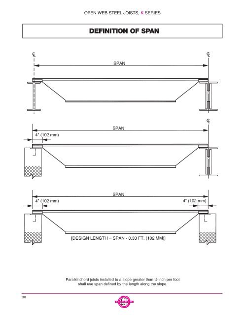
OPEN WEB STEEL JOISTS, K-SERIES DEFINITION OF SPAN Parallel chord joists installed to a slope greater than ¹⁄₂ inch per foot shall use span defined by the length along the slope. 30
- Page 2 and 3: TABLE OF CONTENTS **IMPORTANT NOTIC
- Page 4 and 5: VULCRAFT OF NEW YORK, INC. LOCATION
- Page 6 and 7: JOIST DESIGN COMMENTARY FLOOR VIBRA
- Page 8 and 9: LOAD AND RESISTANCE FACTOR DESIGN T
- Page 10 and 11: VULCRAFT K SERIES / GENERAL INFORMA
- Page 12 and 13: STANDARD LOAD TABLE/OPEN WEB STEEL
- Page 14 and 15: STANDARD LOAD TABLE/OPEN WEB STEEL
- Page 16 and 17: KCS JOISTS EXAMPLE 2 OPTION A: Use
- Page 18 and 19: KCS JOISTS LOAD TABLE (SYSTEME INTE
- Page 20 and 21: STANDARD LOAD TABLE IN METRIC UNITS
- Page 22 and 23: STANDARD LOAD TABLE IN METRIC UNITS
- Page 24 and 25: OPEN WEB STEEL JOISTS, K-SERIES In
- Page 26 and 27: OPEN WEB STEEL JOISTS, K-SERIES 4.5
- Page 28 and 29: OPEN WEB STEEL JOISTS, K-SERIES NUM
- Page 32 and 33: ACCESSORIES AND DETAILS 2.5K SERIES
- Page 34 and 35: ACCESSORIES AND DETAILS K SERIES OP
- Page 36 and 37: ACCESSORIES AND DETAILS BRIDGING RE
- Page 38 and 39: OPEN WEB STEEL JOISTS, K-SERIES TOP
- Page 40 and 41: OPEN WEB STEEL JOISTS, K-SERIES TOP
- Page 42 and 43: ACCESSORIES AND DETAILS LH & DLH SE
- Page 44 and 45: VULCRAFT LH & DLH SERIES / GENERAL
- Page 46 and 47: STANDARD LOAD TABLE/LONG SPAN STEEL
- Page 48 and 49: STANDARD LOAD TABLE DEEP LONGSPAN S
- Page 50 and 51: METRIC LOAD TABLE LONGSPAN STEEL JO
- Page 52 and 53: STANDARD LOAD TABLE IN METRIC UNITS
- Page 54 and 55: STANDARD LOAD TABLE IN METRIC UNITS
- Page 56 and 57: LONGSPAN AND DEEP LONGSPAN STEEL JO
- Page 58 and 59: LONGSPAN AND DEEP LONGSPAN STEEL JO
- Page 60 and 61: LONGSPAN AND DEEP LONGSPAN STEEL JO
- Page 62 and 63: LONGSPAN AND DEEP LONGSPAN STEEL JO
- Page 64 and 65: VULCRAFT SLH / GENERAL INFORMATION
- Page 66 and 67: ACCESSORIES AND DETAILS SLH SERIES
- Page 68 and 69: VULCRAFT LOAD TABLE SUPER LONGSPAN
- Page 70 and 71: SPECIFICATIONS FOR VULCRAFT SUPER L
- Page 72 and 73: SPECIFICATIONS FOR VULCRAFT SUPER L
- Page 74 and 75: SPECIFICATIONS FOR VULCRAFT SUPER L
- Page 76 and 77: VULCRAFT JOIST GIRDERS WHAT ARE JOI
- Page 78 and 79: JOIST GIRDER NOTES If fixed end mom
- Page 80 and 81:
MOMENT CONNECTION DETAILS Presented
- Page 82 and 83:
DESIGN GUIDE WEIGHT TABLE FOR JOIST
- Page 84 and 85:
DESIGN GUIDE WEIGHT TABLE FOR JOIST
- Page 86 and 87:
DESIGN GUIDE WEIGHT TABLE FOR JOIST
- Page 88 and 89:
DESIGN GUIDE WEIGHT TABLE FOR JOIST
- Page 90 and 91:
Based on an allowable tensile stres
- Page 92 and 93:
JOIST GIRDERS DESIGN GUIDE WEIGHT T
- Page 94 and 95:
JOIST GIRDERS DESIGN GUIDE WEIGHT T
- Page 96 and 97:
JOIST GIRDERS DESIGN GUIDE WEIGHT T
- Page 98 and 99:
STANDARD SPECIFICATIONS FOR JOIST G
- Page 100 and 101:
JOIST GIRDERS For cold-formed secti
- Page 102 and 103:
JOIST GIRDERS The designed detail o
- Page 104 and 105:
FIRE-RESISTANCE RATINGS WITH STEEL
- Page 106 and 107:
FIRE-RESISTANCE RATINGS WITH STEEL
- Page 108 and 109:
ECONOMICAL JOIST GUIDE Combined K,
- Page 110 and 111:
ECONOMICAL JOIST GUIDE Combined K,
- Page 112 and 113:
ECONOMICAL JOIST GUIDE Combined K,
- Page 114 and 115:
ECONOMICAL JOIST GUIDE Combined K,
- Page 116 and 117:
ECONOMICAL JOIST GUIDE Combined K,
- Page 118 and 119:
ECONOMICAL JOIST GUIDE Combined K,
- Page 120 and 121:
RECOMMENDED CODE OF STANDARD PRACTI
- Page 122 and 123:
RECOMMENDED CODE OF STANDARD PRACTI
- Page 124 and 125:
RECOMMENDED CODE OF STANDARD PRACTI
- Page 126 and 127:
RECOMMENDED CODE OF STANDARD PRACTI
- Page 128 and 129:
PUBLICATIONS Vulcraft (Refer to bac