Vulcraft_Joist_Catal..
Vulcraft_Joist_Catal..
Vulcraft_Joist_Catal..
- No tags were found...

Create successful ePaper yourself
Turn your PDF publications into a flip-book with our unique Google optimized e-Paper software.
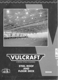
VULCRAFT JOIST GIRDERS<br />
WHAT ARE JOIST GIRDERS?<br />
<strong>Joist</strong> girders are primary framing members. The design<br />
is simple span, supporting equally spaced concentrated<br />
loads from open web steel joists. These concentrated<br />
loads are considered to act at the panel points of the joist<br />
girder.<br />
<strong>Joist</strong> girders are designed to allow for the efficient use of<br />
steel in longer spans for primary framing members.<br />
The following weight tables list joist girders from 20" to<br />
96" deep and spans up to 100 feet. (For depths and<br />
lengths not listed contact <strong>Vulcraft</strong>.) The depth designation<br />
is determined by the nominal depth at the center of the<br />
span, except for offset double pitched girders, where the<br />
depth is determined at the ridge.<br />
The standard configuration of a joist girder is parallel<br />
chord with underslung ends and bottom chord<br />
extensions. (<strong>Joist</strong> girders can be furnished in other<br />
configurations, see below.) The standard depth of bearing<br />
for joist girders is 7 1 / 2 inches at the end of the bearing<br />
seat.*<br />
The standard method of connecting girders to columns is<br />
two 3/4" diameter A325 bolts. A loose connection of the<br />
lower chord to the column or other support is required<br />
during erection in order to stabilize the lower chord<br />
laterally and to help brace the joist girder against<br />
overturning. CAUTION: IF A RIGID CONNECTION OF<br />
THE BOTTOM CHORD IS TO BE MADE TO COLUMN<br />
OR OTHER SUPPORT, IT IS TO BE MADE ONLY<br />
AFTER THE APPLICATION OF THE DEAD LOADS.<br />
THE JOIST GIRDER IS THEN NO LONGER SIMPLY<br />
SUPPORTED AND THE SYSTEM MUST BE<br />
INVESTIGATED FOR CONTINUOUS FRAME ACTION<br />
BY THE SPECIFYING PROFESSIONAL.<br />
<strong>Joist</strong> girders along the perimeter, with joists coming in<br />
from one side only, and those with unbalanced loads<br />
must be designed such that the reactions pass through<br />
the center of the joist girder.<br />
The weight tables list the approximate weight per linear<br />
foot for a joist girder supporting the panel point loads<br />
given by the specifying engineer. NOTE: THE WEIGHT<br />
OF THE JOIST GIRDER MUST BE INCLUDED IN THE<br />
PANEL POINT LOAD. (SEE THE EXAMPLE ON PAGE<br />
80).<br />
For calculating the approximate deflection or checking<br />
ponding the following formula may be used in<br />
determining the approximate moment of inertia of the<br />
joist girder. I JG = 0.027 NPLd<br />
Where N = number of joist spaces, P = panel point load<br />
in kips, L = joist girder length in feet and d = effective<br />
depth of the joist girder in inches. Contact <strong>Vulcraft</strong> if a<br />
more exact joist girder moment of inertia must be known.<br />
*Increase seat depth to 10” if weight of joist girder<br />
appears to the right of the stepped blue lines in the weight<br />
tables.<br />
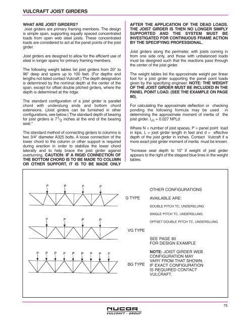
OTHER CONFIGURATIONS<br />
G TYPE<br />
AVAILABLE ARE:<br />
DOUBLE PITCH TC, UNDERSLUNG<br />
SINGLE PITCH TC, UNDERSLUNG<br />
OFFSET DOUBLE PITCH TC, UNDERSLUNG<br />
VG TYPE<br />
SEE PAGE 80<br />
FOR DESIGN EXAMPLE<br />
BG TYPE<br />
NOTE: JOIST GIRDER WEB<br />
CONFIGURATION MAY<br />
VARY FROM THAT SHOWN.<br />
IF EXACT CONFIGURATION<br />
IS REQUIRED CONTACT<br />
VULCRAFT.<br />
75