Vulcraft_Joist_Catal..
Vulcraft_Joist_Catal..
Vulcraft_Joist_Catal..
- No tags were found...
You also want an ePaper? Increase the reach of your titles
YUMPU automatically turns print PDFs into web optimized ePapers that Google loves.
LONGSPAN AND DEEP LONGSPAN STEEL JOISTS, LH- AND DLH-SERIES<br />
103.4 MEMBERS<br />
(a) Chords<br />
The bottom chord shall be designed as an axially<br />
loaded tension member.<br />
The top chord shall be designed as a continuous<br />
member subject to combined axial and bending<br />
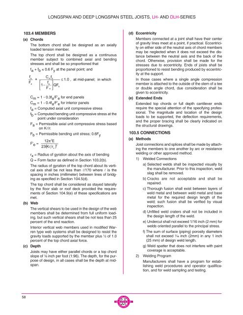
stresses and shall be so proportioned that<br />
f a + f b ≤ 0.6 F y at the panel point; and<br />
C m = 1 - 0.3f a /F' e for end panels<br />
C m = 1 - 0.4f a /F' e for interior panels<br />
f a = Computed axial unit compressive stress<br />
f b = Computed bending unit compressive stress at the<br />
point under consideration<br />
F a = Permissible axial unit compressive stress based<br />
on Kl/r.<br />
F b = Permissible bending unit stress; 0.6F y<br />
F' e =<br />
r x = Radius of gyration about the axis of bending<br />
Q = Form factor as defined in Section 103.2(b).<br />
The radius of gyration of the top chord about its vertical<br />
axis shall be not less than l/170 where l is the<br />
spacing in inches (millimeter) between lines of bridging<br />
as specified in Section 104.5(d).<br />
The top chord shall be considered as stayed laterally<br />
by the floor slab or roof deck provided the requirements<br />
of Section 104.9(e) of these specifications are<br />
met.<br />
(b) Web<br />
The vertical shears to be used in the design of the web<br />
members shall be determined from full uniform loading,<br />
but such vertical shears shall be not less than 25<br />
percent of the end reaction.<br />
Interior vertical web members used in modified Warren<br />
type web systems shall be designed to resist the<br />
gravity loads supported by the member plus ¹⁄₂ of 1.0<br />
percent of the top chord axial force.<br />
(c) Depth<br />
<strong>Joist</strong>s may have either parallel chords or a top chord<br />
slope of ¹⁄₈ inch per foot (1:96). The depth, for the purpose<br />
of design, in all cases shall be the depth at midspan.<br />
(d) Eccentricity<br />
Members connected at a joint shall have their center<br />
of gravity lines meet at a point, if practical. Eccentricity<br />
on either side of the neutral axis of chord members<br />
may be neglected when it does not exceed the distance<br />
between the neutral axis and the back of the<br />
chord. Otherwise, provision shall be made for the<br />
stresses due to eccentricity. Ends of joists shall be<br />
proportioned to resist bending produced by eccentricity<br />
at the support.<br />
In those cases where a single angle compression<br />
member is attached to the outside of the stem of a tee<br />
or double angle chord, due consideration shall be<br />
given to eccentricity.<br />
(e) Extended Ends<br />
Extended top chords or full depth cantilever ends<br />
require the special attention of the specifying professional.<br />
The magnitude and location of the design<br />
loads to be supported, the deflection requirements,<br />
and the proper bracing shall be clearly indicated on<br />
the structural drawings.<br />
103.5 CONNECTIONS<br />
(a) Methods<br />
<strong>Joist</strong> connections and splices shall be made by attaching<br />
the members to one another by arc or resistance<br />
welding or other approved method.<br />
1) Welded Connections<br />
a) Selected welds shall be inspected visually by<br />
the manufacturer. Prior to this inspection, weld<br />
slag shall be removed.<br />
b) Cracks are not acceptable and shall be<br />
repaired.<br />
c) Thorough fusion shall exist between layers of<br />
weld metal and between weld metal and base<br />
metal for the required design length of the<br />
weld; such fusion shall be verified by visual<br />
inspection.<br />
d) Unfilled weld craters shall not be included in<br />
the design length of the weld.<br />
e) Undercut shall not exceed 1/16 inch (2 mm) for<br />
welds oriented parallel to the principal stress.<br />
f) The sum of surface (piping) porosity diameters<br />
shall not exceed ¹⁄₁₆ inch (2mm) in any 1 inch<br />
(25 mm) of design weld length.<br />
g) Weld spatter that does not interfere with paint<br />
coverage is acceptable.<br />
2) Welding Program<br />
Manufacturers shall have a program for establishing<br />
weld procedures and operator qualification,<br />
and for weld sampling and testing.<br />
58


