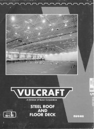
Vulcraft_Joist_Catal..
Vulcraft_Joist_Catal..
Vulcraft_Joist_Catal..
- No tags were found...

You also want an ePaper? Increase the reach of your titles
YUMPU automatically turns print PDFs into web optimized ePapers that Google loves.
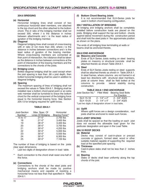
SPECIFICATIONS FOR VULCRAFT SUPER LONGSPAN STEEL JOISTS SLH-SERIES<br />
204.6 BRIDGING<br />
(a) Horizontal<br />
Horizontal bridging lines shall consist of two<br />
continuous horizontal steel members, one attached<br />
to the top chord and the other attached to the bottom<br />
chord. The l/r ratio of the bridging member shall not<br />
exceed 300, where l is the distance in inches<br />
between attachments and r is the least radius of<br />
gyration of the bridging member.<br />
(b) Diagonal<br />
Diagonal bridging lines shall consist of cross-bracing<br />
with l/r ratio of not more than 200, where l is the<br />
distance in inches between connections and r is the<br />
least radius of gyration of the bracing member.<br />
Where cross-bracing members are connected at<br />
their point of intersection, the l distance shall be taken<br />
as the distance in inches between connections at the<br />
point of intersection of the bracing members and the<br />
connections to the chords of the joists.<br />
(c) Bridging Lines<br />
Bolted diagonal bridging shall be used except when<br />
the joist spacing is less than .66 x joist depth, then<br />
bolted horizontal bridging shall be used in addition to<br />
diagonal bridging.<br />
(d) Spacing<br />
The maximum spacing of lines of bridging shall not<br />
exceed the values in Table 204.6.1. Bridging shall be<br />
installed near a bottom chord panel point or an extra<br />
web member shall be furnished to brace the bottom<br />
chord for the vertical component of the bridging force<br />
equal to the horizontal bracing force. See Section<br />
204.13 for bridging required for uplift forces.<br />
TABLE 204.6.1<br />
<strong>Joist</strong>-Section Max. Spac. Of Horizontal<br />
Number* Lines Of Bridging Bracing Force**<br />
15 to 17 21'-0" 2,700 Ibs<br />
18 21'-0" 3,400 Ibs<br />
19 26'-0" 3,400 Ibs<br />
20 26'-0" 3,700 Ibs<br />
21 30'-0" 4,200 Ibs<br />
22 30'-0" 5,000 Ibs<br />
23 30'-0" 5,500 Ibs<br />
24 30'-0" 6,300 Ibs<br />
25 30'-0" 7,100 Ibs<br />
The number of lines of bridging is based on the joists<br />
clear span dimensions.<br />
* Last two digits of designation shown in load table.<br />
** Each connection to the chord shall resist one-half of<br />
this force.<br />
(e) Connections<br />
Connections to the chords of the steel joists and<br />
bridging anchors shall be made by positive<br />
mechanical means and capable of resisting a<br />
horizontal force not less than that specified in Table<br />
204.6.1.<br />
(f) Bottom Chord Bearing <strong>Joist</strong>s<br />
It is not recommended that SLH-Series joists be<br />
used in bottom chord bearing configuration.<br />
204.7 INSTALLATION OF BRIDGING<br />
All bridging and bridging anchors shall be completely<br />
installed before construction loads are placed on the<br />
joists. Bridging shall support the top and bottom chords<br />
against lateral movement during the construction period<br />
and shall hold the steel joists in the approximate position<br />
as shown on the plans.<br />
The ends of all bridging lines terminating at walls or<br />
beams shall be anchored thereto.<br />
204.8 END ANCHORAGE<br />
(a) Masonry and Concrete<br />
Ends of SLH Series <strong>Joist</strong>s resting on steel bearing<br />
plates on masonry or structural concrete shall be<br />
attached thereto as shown Table 204.8.1.<br />
(b) Steel<br />
Ends of SLH Series <strong>Joist</strong>s resting on steel supports<br />
shall be attached thereto as shown in Table 204.8.1.<br />
In steel frames, where columns are not framed in at<br />
least two directions with structural steel members,<br />
joists at column lines shall be field bolted at the<br />
columns to provide lateral stability during<br />
construction.<br />
TABLE 204.8.1 END ANCHORAGE<br />
<strong>Joist</strong> Section No.* Fillet Weld Bearing Seat Bolts<br />
For Erection<br />
SLH 15-18 2 - 1/4" x 2" 2 - 3/4" A325<br />
SLH 19-25 2 - 1/4" x 4" 2 - 3/4" A325<br />
*Last two digits of designation shown in load table.<br />
(c) Uplift<br />
Where uplift forces are a design consideration, roof<br />
joists shall be anchored to resist such forces.<br />
204.9 JOIST SPACING<br />
<strong>Joist</strong>s shall be spaced so that the loading on each joist<br />
does not exceed the allowable load given for the<br />
particular designation and span in the Load Table.<br />
204.10 ROOF DECKS<br />
(a) Material<br />
Decks may consist of cast-in-place or precast<br />
concrete or gypsum, formed steel, wood or other<br />
suitable material capable of supporting the required<br />
load at the specified joist spacing.<br />
(b) Thickness<br />
Cast-in-place slabs shall not be less than 2 inches<br />
thick.<br />
(c) Bearing<br />
Slabs or decks shall bear uniformly along the top<br />
chords of the joist.<br />
72