Vulcraft_Joist_Catal..
Vulcraft_Joist_Catal..
Vulcraft_Joist_Catal..
- No tags were found...

Create successful ePaper yourself
Turn your PDF publications into a flip-book with our unique Google optimized e-Paper software.
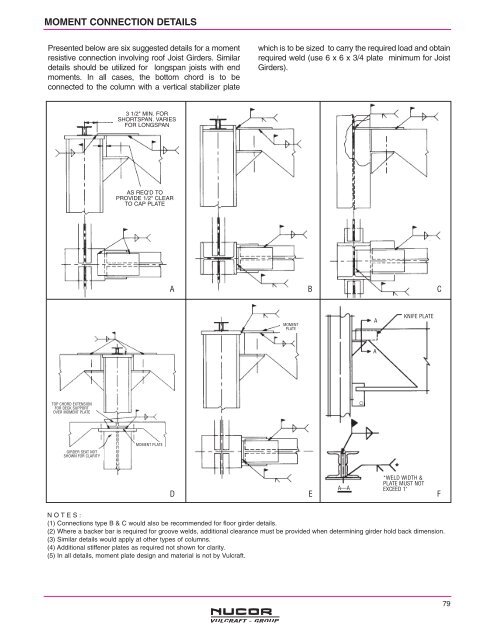
MOMENT CONNECTION DETAILS<br />
Presented below are six suggested details for a moment<br />
resistive connection involving roof <strong>Joist</strong> Girders. Similar<br />
details should be utilized for longspan joists with end<br />
moments. In all cases, the bottom chord is to be<br />
connected to the column with a vertical stabilizer plate<br />
which is to be sized to carry the required load and obtain<br />
required weld (use 6 x 6 x 3/4 plate minimum for <strong>Joist</strong><br />
Girders).<br />
3 1/2" MIN. FOR<br />
SHORTSPAN. VARIES<br />
FOR LONGSPAN<br />
AS REQ'D TO<br />
PROVIDE 1/2" CLEAR<br />
TO CAP PLATE<br />
A<br />
B<br />
C<br />
MOMENT<br />
PLATE<br />
A<br />
KNIFE PLATE<br />
A<br />
TOP CHORD EXTENSION<br />
FOR DECK SUPPORT<br />
OVER MOMENT PLATE<br />
GIRDER SEAT NOT<br />
SHOWN FOR CLARITY<br />
MOMENT PLATE<br />
D<br />
E<br />
A—A<br />
*WELD WIDTH &<br />
PLATE MUST NOT<br />
EXCEED 1"<br />
F<br />
N O T E S :<br />
(1) Connections type B & C would also be recommended for floor girder details.<br />
(2) Where a backer bar is required for groove welds, additional clearance must be provided when determining girder hold back dimension.<br />
(3) Similar details would apply at other types of columns.<br />
(4) Additional stiffener plates as required not shown for clarity.<br />
(5) In all details, moment plate design and material is not by <strong>Vulcraft</strong>.<br />
79