

Xeon-Phi-Coprocessor-Datasheet
Xeon-Phi-Coprocessor-Datasheet
Xeon-Phi-Coprocessor-Datasheet

Create successful ePaper yourself
Turn your PDF publications into a flip-book with our unique Google optimized e-Paper software.
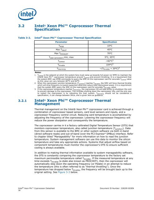
3.2 Intel ® <strong>Xeon</strong> <strong>Phi</strong> <strong>Coprocessor</strong> Thermal<br />
Specification<br />
Table 3-2.<br />
Intel ® <strong>Xeon</strong> <strong>Phi</strong> <strong>Coprocessor</strong> Thermal Specification<br />
Parameter<br />
Specification<br />
T RISE 10°C<br />
Max T INLET 45°C<br />
Max T EXHAUST 70°C<br />
T case (processor) min, max 5°C, 95°C<br />
T control ~82°C 1<br />
T throttle 104°C 2<br />
T thermtrip ~(T throttle + 20°C) 3<br />
Notes:<br />
1. T control is the setpoint at which the system fans must ramp up towards full power (or RPM) to maintain the<br />
Intel® <strong>Xeon</strong> <strong>Phi</strong> coprocessor temperature around T control and prevent throttling. It is a requirement that<br />
the system BMC use IPMB commands to query the SMC on the coprocessor card for accurate T control value<br />
as this value can vary between 80°C and 84°C.<br />
2. When the coprocessor junction temperature (T junction ) reaches T throttle , the SMC will force thermal throttle<br />
which will drop frequency to lowest supported value and reduce total coprocessor power. It is a requirement<br />
that the system BMC query the SMC on the coprocessor card for accurate T throttle value.<br />
3. If the coprocessor temperature reaches T thermtrip , the coprocessor OS will take action to shutdown the card<br />
to prevent damage to the coprocessor. This includes shutting down the coprocessor VRs, and the only way<br />
to restart the coprocessor is by rebooting the host system. T thermtrip should not be considered a<br />
specification; it can change between SKUs, and is given here as guidance.<br />
3.2.1 Intel ® <strong>Xeon</strong> <strong>Phi</strong> <strong>Coprocessor</strong> Thermal<br />
Management<br />
Thermal management on the Intel® <strong>Xeon</strong> <strong>Phi</strong> coprocessor card is achieved through a<br />
combination of coprocessor based sensors, card level sensors and inputs, and a<br />
coprocessor frequency control circuit. Reducing card temperature is accomplished by<br />
adjusting the frequency of the coprocessor. Lowering the coprocessor frequency will<br />
reduce the power dissipation and consequently the temperature.<br />
The coprocessor carries in it a factory calibrated Digital Temperature Sensor (DTS) that<br />
monitors coprocessor temperature, also called junction temperature (T junction ). Data<br />
from this sensor is available to the BMC or other system software via both in-band<br />
(direct software reads) and out-of-band (over the PCI Express* SMBus) interface. Refer<br />
to chapter titled “Manageability” for more information on how to read the junction<br />
temperature. System management software can use this data to monitor the silicon<br />
temperature and take any appropriate actions. Systems that adjust airflow based on<br />
component temperatures must monitor the coprocessor’s DTS to ensure sufficient<br />
cooling is always available.<br />
In addition to making thermal information available to system manageability software,<br />
the DTS is constantly comparing the coprocessor temperature to the factory set<br />
maximum permissible temperature called T throttle . If the measured temperature at any<br />
time exceeds T throttle (a state also known as PROCHOT), then the coprocessor will<br />
automatically step down the operating frequency (or Pstate) in an attempt to reduce<br />
the temperature (this is often referred to as “thermal throttling”). Once the<br />
temperature has dropped below T throttle , the frequency will be brought back up to the<br />
original setting. See Figure 3-3 below.<br />
Intel ® <strong>Xeon</strong> <strong>Phi</strong> <strong>Coprocessor</strong> <strong>Datasheet</strong><br />
18<br />
Document ID Number: 328209 003EN